PIC18F2480/2580/4480/4580
1. Configure the EUSART for the desired mode.
19.2.5
BREAK CHARACTER SEQUENCE
2. Set the TXEN and SENDB bits to set up the
Break character.
The Enhanced EUSART module has the capability of
sending the special Break character sequences that
are required by the LIN/J2602 bus standard. The Break
character transmit consists of a Start bit, followed by
twelve ‘0’ bits and a Stop bit. The Frame Break charac-
ter is sent whenever the SENDB and TXEN bits
(TXSTA<3> and TXSTA<5>) are set while the Transmit
Shift register is loaded with data. Note that the value of
data written to TXREG will be ignored and all ‘0’s will
be transmitted.
3. Load the TXREG with a dummy character to
initiate transmission (the value is ignored).
4. Write ‘55h’ to TXREG to load the Sync character
into the transmit FIFO buffer.
5. After the Break has been sent, the SENDB bit is
reset by hardware. The Sync character now
transmits in the preconfigured mode.
When the TXREG becomes empty, as indicated by the
TXIF, the next data byte can be written to TXREG.
The SENDB bit is automatically reset by hardware after
the corresponding Stop bit is sent. This allows the user
to preload the transmit FIFO with the next transmit byte
following the Break character (typically, the Sync
character in the LIN/J2602 specification).
19.2.6
RECEIVING A BREAK CHARACTER
The Enhanced USART module can receive a Break
character in two ways.
Note that the data value written to the TXREG for the
Break character is ignored. The write simply serves the
purpose of initiating the proper sequence.
The first method forces configuration of the baud rate
at a frequency of 9/13 the typical speed. This allows for
the Stop bit transition to be at the correct sampling loca-
tion (13 bits for Break versus Start bit and 8 data bits for
typical data).
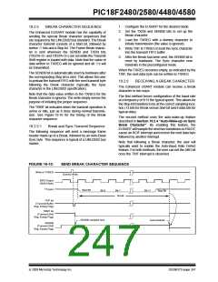
The TRMT bit indicates when the transmit operation is
active or Idle, just as it does during normal transmis-
sion. See Figure 19-10 for the timing of the Break
character sequence.
The second method uses the auto-wake-up feature
described in Section 19.2.4 “Auto-Wake-up on Sync
Break Character”. By enabling this feature, the
EUSART will sample the next two transitions on RX/DT,
cause an RCIF interrupt and receive the next data byte
followed by another interrupt.
19.2.5.1
Break and Sync Transmit Sequence
The following sequence will send a message frame
header made up of a Break, followed by an Auto-Baud
Sync byte. This sequence is typical of a LIN/J2602 bus
master.
Note that following a Break character, the user will
typically want to enable the Auto-Baud Rate Detect
feature. For both methods, the user can set the ABD bit
once the TXIF interrupt is observed.
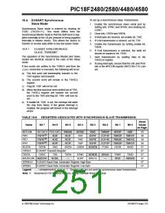
FIGURE 19-10:
SEND BREAK CHARACTER SEQUENCE
Write to TXREG
Dummy Write
BRG Output
(Shift Clock)
TX (pin)
Start Bit
Bit 0
Bit 1
Break
Bit 11
Stop Bit
TXIF bit
(Transmit Buffer
Reg. Empty Flag)
TRMT bit
(Transmit Shift
Reg. Empty Flag)
SENDB sampled here
Auto-Cleared
SENDB
(Transmit Shift
Reg. Empty Flag)
© 2009 Microchip Technology Inc.
DS39637D-page 247

 MICROCHIP [ MICROCHIP ]