PIC18CXX2
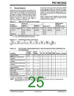
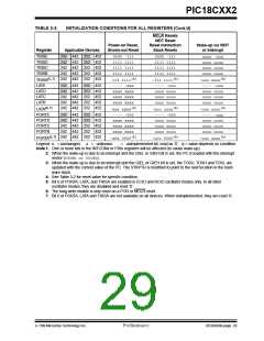
TABLE 3-3:
Register
INITIALIZATION CONDITIONS FOR ALL REGISTERS (Cont.’d)
MCLR Resets
WDT Reset
Power-on Reset,
Brown-out Reset
Reset Instruction
Stack Resets
Wake-up via WDT
or Interrupt
Applicable Devices
TRISE
TRISD
TRISC
TRISB
TRISA(5, 7)
LATE
242 442 252 452
242 442 252 452
242 442 252 452
242 442 252 452
242 442 252 452
0000 -111
1111 1111
1111 1111
1111 1111
-111 1111(5)
---- -xxx
xxxx xxxx
xxxx xxxx
xxxx xxxx
-xxx xxxx(5)
---- -000
xxxx xxxx
xxxx xxxx
xxxx xxxx
0000 -111
1111 1111
1111 1111
1111 1111
-111 1111(5)
---- -uuu
uuuu uuuu
uuuu uuuu
uuuu uuuu
-uuu uuuu(5)
---- -000
uuuu uuuu
uuuu uuuu
uuuu uuuu
uuuu -uuu
uuuu uuuu
uuuu uuuu
uuuu uuuu
-uuu uuuu(5)
---- -uuu
uuuu uuuu
uuuu uuuu
uuuu uuuu
-uuu uuuu(5)
---- -uuu
uuuu uuuu
uuuu uuuu
uuuu uuuu
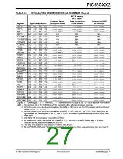
242 442 252 452
242 442 252 452
242 442 252 452
242 442 252 452
242 442 252 452
LATD
LATC
LATB
LATA(5, 7)
PORTE
PORTD
PORTC
PORTB
242 442 252 452
242 442 252 452
242 442 252 452
242 442 252 452
242 442 252 452
PORTA(5, 7)
-x0x 0000(5)
-u0u 0000(5)
-uuu uuuu(5)
Legend: u = unchanged, x = unknown, -= unimplemented bit, read as ’0’, q = value depends on condition
Note 1: One or more bits in the INTCONx or PIRx registers will be affected (to cause wake-up).
2: When the wake-up is due to an interrupt and the GIEL or GIEH bit is set, the PC is loaded with the interrupt
vector (0008h or 0018h).
3: When the wake-up is due to an interrupt and the GIEL or GIEH bit is set, the TOSU, TOSH and TOSL are
updated with the current value of the PC. The STKPTR is modified to point to the next location in the hard-
ware stack.
4: See Table 3-2 for reset value for specific condition.
5: Bit 6 of PORTA, LATA, and TRISA are enabled in ECIO and RCIO oscillator modes only. In all other
oscillator modes, they are disabled and read ’0’.
6: The long write enable is only reset on a POR or MCLR reset.
7: Bit 6 of PORTA, LATA and TRISA are not available on all devices. When unimplemented, they are read ’0’.
7/99 Microchip Technology Inc.
Preliminary
DS39026B-page 29

 MICROCHIP [ MICROCHIP ]