PIC18CXX2
Since the time-outs occur from the POR pulse, if MCLR
is kept low long enough, the time-outs will expire.
Bringing MCLR high will begin execution immediately
(Figure 3-5). This is useful for testing purposes or to
synchronize more than one PIC18CXXX device operat-
ing in parallel.
3.6
Time-out Sequence
On power-up, the time-out sequence is as follows: First,
PWRT time-out is invoked after the POR time delay has
expired. Then, OST is activated. The total time-out will
vary based on oscillator configuration and the status of
the PWRT. For example, in RC mode with the PWRT
disabled, there will be no time-out at all. Figure 3-3,
Figure 3-4, Figure 3-5, Figure 3-6 and Figure 3-7
depict time-out sequences on power-up.
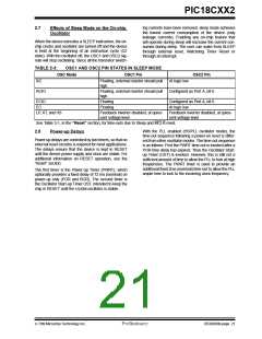
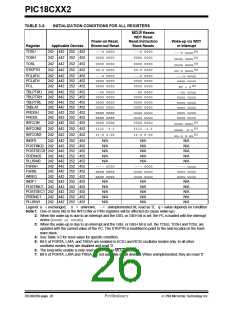
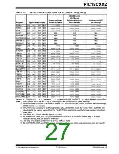
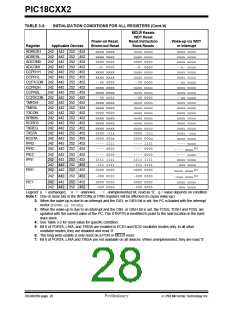
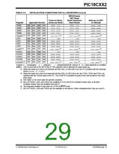
Table 3-2 shows the reset conditions for some Special
Function Registers, while Table 3-3 shows the reset
conditions for all the registers.
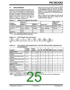
TABLE 3-1:
TIME-OUT IN VARIOUS SITUATIONS
Power-up (2)
Wake-up from
SLEEP or
Oscillator Switch
Oscillator
Configuration
PWRTE = 0
PWRTE = 1
Brown-out (2)
HS with PLL enabled (1)
HS, XT, LP
72 ms + 1024Tosc + 2ms 1024Tosc + 2 ms 72 ms + 1024Tosc + 2ms 1024Tosc + 2 ms
72 ms + 1024Tosc
72 ms
1024Tosc
72 ms + 1024Tosc
72 ms
1024Tosc
EC
—
—
—
External RC
72 ms
—
72 ms
Note 1: 2 ms = Nominal time required for the 4x PLL to lock.
2: 72 ms is the nominal power-up timer delay
Register 3-1: RCON Register Bits and Positions
R/W-0
R/W-0
U-0
R/W-1
R/W-1
R/W-1
R/W-1
R/W-1
BOR
IPEN
LWRT
—
RI
TO
PD
POR
bit 7
bit 0
TABLE 3-2:
STATUS BITS, THEIR SIGNIFICANCE AND THE INITIALIZATION CONDITION FOR
RCON REGISTER
Program
Counter
RCON
Register
Condition
RI TO PD POR BOR STKFUL STKUNF
Power-on Reset
0000h
0000h
00-1 1100
00-u uuuu
1
u
1
u
1
u
0
u
0
u
u
u
u
u
MCLR Reset during normal
operation
Software Reset during normal
operation
0000h
0u-0 uuuu
0u-u uu11
0u-u uu11
0
u
u
u
u
u
u
u
u
u
u
u
u
u
u
u
u
1
u
1
u
Stack Full Reset during normal 0000h
operation
Stack Underflow Reset during
normal operation
0000h
MCLR Reset during SLEEP
WDT Reset
0000h
0000h
PC + 2
0000h
00-u 10uu
0u-u 01uu
uu-u 00uu
0u-1 11u0
uu-u 00uu
u
1
u
1
u
1
0
0
1
1
0
1
0
1
0
u
u
u
1
u
u
u
u
0
u
u
u
u
u
u
u
u
u
u
u
WDT Wake-up
Brown-out Reset
PC + 2(1)
Interrupt wake-up from SLEEP
Legend: u = unchanged, x = unknown, — = unimplemented bit read as '0'.
Note 1: When the wake-up is due to an interrupt and the GIEH or GIEL bits are set, the PC is loaded with the
interrupt vector (0x000008h or 0x000018h).
7/99 Microchip Technology Inc.
Preliminary
DS39026B-page 25

 MICROCHIP [ MICROCHIP ]