PIC18CXX2
The following steps are needed to setup the LVD
module:
17.2
Operation
Depending on the power source for the device voltage,
the voltage normally decreases relatively slowly. This
means that the LVD module does not need to be con-
stantly operating. To decrease the current require-
ments, the LVD circuitry only needs to be enabled for
short periods, where the voltage is checked. After
doing the check, the LVD module may be disabled.
1. Write the value to the LVDL3:LVDL0 bits (LVD-
CON register), which selects the desired LVD
Trip Point.
2. Ensure that LVD interrupts are disabled (the
LVDIE bit is cleared or the GIE bit is cleared).
3. Enable the LVD module (Set the LVDEN bit in
the LVDCON register).
Each time that the LVD module is enabled, the circuitry
requires some time to stabilize. After the circuitry has
stabilized, all status flags may be cleared. The module
will then indicate the proper state of the system.
4. Wait for the LVD module to stabilize (the IRVST
bit to become set).
5. Clear the LVD interrupt flag, which may have
falsely become set until the LVD module has sta-
bilized (clear the LVDIF bit).
6. Enable the LVD interrupt (set the LVDIE and the
GIE bits).
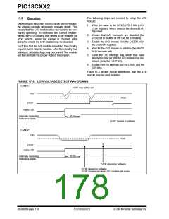
Figure 17-3 shows typical waveforms that the LVD
module may be used to detect.
FIGURE 17-3: LOW VOLTAGE DETECT WAVEFORMS
CASE 1:
LVDIF may not be set
VDD
.
VLVD
LVDIF
Enable LVD
50 ms
Internally Generated
Reference stable
LVDIF cleared in software
CASE 2:
VDD
VLVD
LVDIF
Enable LVD
50 ms
Internally Generated
Reference stable
LVDIF cleared in software
LVDIF cleared in software,
LVDIF remains set since LVD condition still exists
DS39026B-page 178
Preliminary
7/99 Microchip Technology Inc.

 MICROCHIP [ MICROCHIP ]