PIC18F6525/6621/8525/8621
6.1
Program Memory Modes and the
External Memory Interface
6.0
EXTERNAL MEMORY
INTERFACE
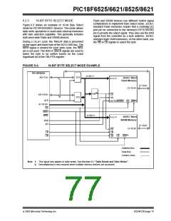
As previously noted, PIC18F8525/8621 controllers are
capable of operating in any one of four program mem-
ory modes using combinations of on-chip and external
program memory. The functions of the multiplexed port
pins depends on the program memory mode selected,
as well as the setting of the EBDIS bit.
Note: The external memory interface is not
implemented on PIC18F6525/6621 (64-pin)
devices.
The external memory interface is a feature of the
PIC18F8525/8621 devices that allows the controller to
access external memory devices (such as Flash,
EPROM, SRAM, etc.) as program or data memory.
In Microprocessor Mode, the external bus is always
active and the port pins have only the external bus
function.
The physical implementation of the interface uses
27 pins. These pins are reserved for external address/
data bus functions; they are multiplexed with I/O port
pins on four ports. Three I/O ports are multiplexed with
the address/data bus, while the fourth port is multiplexed
with the bus control signals. The I/O port functions are
enabled when the EBDIS bit in the MEMCON register is
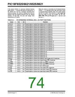
set (see Register 6-1). A list of the multiplexed pins and
their functions is provided in Table 6-1.
In Microcontroller Mode, the bus is not active and
the pins have their port functions only. Writes to the
MEMCOM register are not permitted.
In Microprocessor with Boot Block or Extended
Microcontroller Mode, the external program memory
bus shares I/O port functions on the pins. When the
device is fetching or doing table read/table write oper-
ations on the external program memory space, the
pins will have the external bus function. If the device is
fetching and accessing internal program memory loca-
tions only, the EBDIS control bit will change the pins
from external memory to I/O port functions. When
EBDIS = 0, the pins function as the external bus.
When EBDIS = 1, the pins function as I/O ports.
As implemented in the PIC18F8525/8621 devices, the
interface operates in a similar manner to the external
memory interface introduced on PIC18C601/801 micro-
controllers. The most notable difference is that the
interface on PIC18F8525/8621 devices only operates in
16-bit modes. The 8-bit mode is not supported.
For a more complete discussion of the operating modes
that use the external memory interface, refer to
Section 4.1.1“PIC18F6525/6621/8525/8621Program
Memory Modes”.
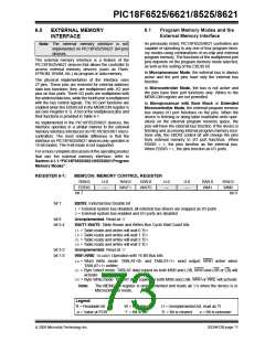
REGISTER 6-1:
MEMCON: MEMORY CONTROL REGISTER
R/W-0
EBDIS
U-0
—
R/W-0
WAIT1
R/W-0
WAIT0
U-0
—
U-0
—
R/W-0
WM1
R/W-0
WM0
bit 7
bit 0
bit 7
EBDIS: External Bus Disable bit
1= External system bus disabled, all external bus drivers are mapped as I/O ports
0= External system bus enabled and I/O ports are disabled
bit 6
Unimplemented: Read as ‘0’
bit 5-4
WAIT1:WAIT0: Table Reads and Writes Bus Cycle Wait Count bits
11= Table reads and writes will wait 0 TCY
10= Table reads and writes will wait 1 TCY
01= Table reads and writes will wait 2 TCY
00= Table reads and writes will wait 3 TCY
bit 3-2
bit 1-0
Unimplemented: Read as ‘0’
WM1:WM0: TBLWRTOperation with 16-Bit Bus bits
1x= Word Write mode: TABLAT<0> and TABLAT<1> word output, WRH active when
TABLAT<1> written
01= Byte Select mode: TABLAT data copied on both MSB and LSB, WRH and (UB or LB) will
activate
00= Byte Write mode: TABLAT data copied on both MSB and LSB, WRH or WRL will activate
Note:
The MEMCON register is unimplemented and reads all ‘0’s when the device is in
Microcontroller mode.
Legend:
R = Readable bit
-n = Value at POR
W = Writable bit
‘1’ = Bit is set
U = Unimplemented bit, read as ‘0’
‘0’ = Bit is cleared x = Bit is unknown
2005 Microchip Technology Inc.
DS39612B-page 71

 MICROCHIP [ MICROCHIP ]