PIC18F6525/6621/8525/8621
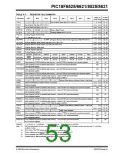
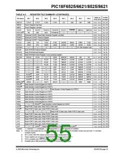
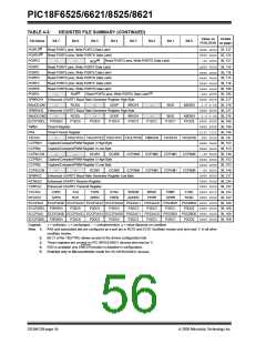
TABLE 4-3:
REGISTER FILE SUMMARY (CONTINUED)
Value on
POR, BOR on page:
Details
File Name
(3)
Bit 7
Bit 6
Bit 5
Bit 4
Bit 3
Bit 2
Bit 1
Bit 0
PORTJ
PORTH
Read PORTJ pins, Write PORTJ Data Latch
xxxx xxxx 35, 127
0000 xxxx 35, 124
--xx xxxx 36, 121
(3)
Read PORTH pins, Write PORTH Data Latch
(4)
PORTG
—
—
Read PORTG pins, Write PORTG Data Latch
RG5
PORTF
PORTE
PORTD
PORTC
PORTB
PORTA
Read PORTF pins, Write PORTF Data Latch
Read PORTE pins, Write PORTE Data Latch
Read PORTD pins, Write PORTD Data Latch
Read PORTC pins, Write PORTC Data Latch
x000 0000 36, 119
xxxx xxxx 36, 116
xxxx xxxx 36, 113
xxxx xxxx 36, 110
xxxx xxxx 36, 108
-x0x 0000 36, 105
0000 0000 36, 217
Read PORTB pins, Write PORTB Data Latch
(1)
(1)
—
RA6
Read PORTA pins, Write PORTA Data Latch
SPBRGH1 Enhanced USART1 Baud Rate Generator Register High Byte
BAUDCON1 RCIDL SCKP BRG16
SPBRGH2 Enhanced USART2 Baud Rate Generator Register High Byte
—
—
—
WUE
ABDEN -1-0 0-00 36, 216
0000 0000 36, 217
BAUDCON2
—
RCIDL
P1DC6
—
SCKP
BRG16
P1DC3
—
WUE
ABDEN -1-0 0-00 36, 216
ECCP1DEL P1RSEN
P1DC5
P1DC4
P1DC2
P1DC1
P1DC0
0000 0000 36, 168
0000 0000 36, 148
1111 1111 36, 148
TMR4
Timer4 Register
PR4
Timer4 Period Register
T4CON
—
T4OUTPS3 T4OUTPS2 T4OUTPS1 T4OUTPS0 TMR4ON T4CKPS1 T4CKPS0 -000 0000 36, 147
CCPR4H
CCPR4L
CCP4CON
CCPR5H
CCPR5L
CCP5CON
SPBRG2
RCREG2
TXREG2
TXSTA2
RCSTA2
Capture/Compare/PWM Register 4 High Byte
Capture/Compare/PWM Register 4 Low Byte
xxxx xxxx 36, 153
xxxx xxxx 36, 153
—
—
DC4B1
DC4B0
CCP4M3
CCP4M2
CCP5M2
CCP4M1
CCP5M1
CCP4M0 --00 0000 36, 149
xxxx xxxx 36, 153
Capture/Compare/PWM Register 5 High Byte
Capture/Compare/PWM Register 5 Low Byte
xxxx xxxx 36, 153
—
—
DC5B1
DC5B0
CCP5M3
CCP5M0 --00 0000 36, 149
0000 0000 36, 217
Enhanced USART2 Baud Rate Generator Register Low Byte
Enhanced USART2 Receive Register
0000 0000 36, 224
Enhanced USART2 Transmit Register
0000 0000 36, 222
CSRC
SPEN
TX9
RX9
TXEN
SREN
SYNC
CREN
SENDB
ADDEN
BRGH
FERR
TRMT
OERR
TX9D
RX9D
0000 0010 36, 222
0000 000x 36, 222
ECCP3AS ECCP3ASE ECCP3AS2 ECCP3AS1 ECCP3AS0 PSS3AC1 PSS3AC0 PSS3BD1 PSS3BD0 0000 0000 36, 169
ECCP3DEL P3RSEN P3DC6 P3DC5 P3DC4 P3DC3 P3DC2 P3DC1 P3DC0 0000 0000 36, 168
ECCP2AS ECCP2ASE ECCP2AS2 ECCP2AS1 ECCP2AS0 PSS2AC1 PSS2AC0 PSS2BD1 PSS2BD0 0000 0000 36, 169
ECCP2DEL P2RSEN P2DC6 P2DC5 P2DC4 P2DC3 P2DC2 P2DC1 P2DC0 0000 0000 36, 168
x= unknown, u= unchanged, – = unimplemented, q= value depends on condition
Legend:
Note 1:
RA6 and associated bits are configured as a port pin in RCIO and ECIO Oscillator modes only and read ‘0’ in all other
oscillator modes.
2:
3:
4:
Bit 21 of the TBLPTRU allows access to the device configuration bits.
These registers are unused on PIC18F6525/6621 devices and read as ‘0’.
RG5 is available only if MCLR function is disabled in configuration.
5: Enabled only in Microcontroller mode for PIC18F8525/8621 devices.
DS39612B-page 54
2005 Microchip Technology Inc.

 MICROCHIP [ MICROCHIP ]