PIC18F6525/6621/8525/8621
4.3
Fast Register Stack
4.4
PCL, PCLATH and PCLATU
A “fast interrupt return” option is available for interrupts.
A fast register stack is provided for the STATUS,
WREG and BSR registers and is only one in depth. The
stack is not readable or writable and is loaded with the
current value of the corresponding register when the
processor vectors for an interrupt. The values in the
registers are then loaded back into the working
registers if the FAST RETURN instruction is used to
return from the interrupt.
The Program Counter (PC) specifies the address of the
instruction to fetch for execution. The PC is 21 bits
wide. The low byte is called the PCL register; this reg-
ister is readable and writable. The high byte is called
the PCH register. This register contains the PC<15:8>
bits and is not directly readable or writable; updates to
the PCH register may be performed through the
PCLATH register. The upper byte is called PCU. This
register contains the PC<20:16> bits and is not directly
readable or writable; updates to the PCU register may
be performed through the PCLATU register.
A low or high priority interrupt source will push values
into the stack registers. If both low and high priority
interrupts are enabled, the stack registers cannot be
used reliably for low priority interrupts. If a high priority
interrupt occurs while servicing a low priority interrupt,
the stack register values stored by the low priority
interrupt will be overwritten.
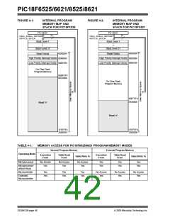
The PC addresses bytes in the program memory. To
prevent the PC from becoming misaligned with word
instructions, the LSB of the PCL is fixed to a value of
‘0’. The PC increments by 2 to address sequential
instructions in the program memory.
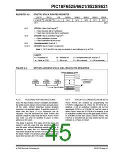
If high priority interrupts are not disabled during low
priority interrupts, users must save the key registers in
software during a low priority interrupt.
The CALL, RCALL, GOTOand program branch instruc-
tions write to the program counter directly. For these
instructions, the contents of PCLATH and PCLATU are
not transferred to the program counter.
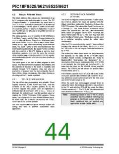
If no interrupts are used, the fast register stack can be
used to restore the STATUS, WREG and BSR registers
at the end of a subroutine call. To use the fast register
stack for a subroutine call, a FAST CALL instruction
must be executed.
The contents of PCLATH and PCLATU will be
transferred to the program counter by an operation that
writes PCL. Similarly, the upper two bytes of the
program counter will be transferred to PCLATH and
PCLATU by an operation that reads PCL. This is useful
for computed offsets to the PC (see Section 4.8.1
“Computed GOTO”).
Example 4-1 shows a source code example that uses
the fast register stack.
EXAMPLE 4-1:
FAST REGISTER STACK
CODE EXAMPLE
;STATUS, WREG, BSR
;SAVED IN FAST REGISTER
;STACK
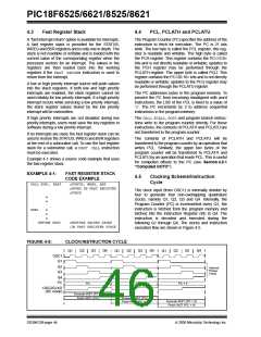
4.5
Clocking Scheme/Instruction
Cycle
CALL SUB1, FAST
The clock input (from OSC1) is internally divided by
four to generate four non-overlapping quadrature
clocks, namely Q1, Q2, Q3 and Q4. Internally, the
Program Counter (PC) is incremented every Q1, the
instruction is fetched from the program memory and
latched into the Instruction Register (IR) in Q4. The
instruction is decoded and executed during the
following Q1 through Q4. The clocks and instruction
execution flow are shown in Figure 4-5.
•
•
SUB1
•
•
•
RETURN FAST
;RESTORE VALUES SAVED
;IN FAST REGISTER STACK
FIGURE 4-5:
CLOCK/INSTRUCTION CYCLE
Q2
Q3
Q4
Q2
Q3
Q4
Q2
Q3
Q4
Q1
Q1
Q1
OSC1
Q1
Q2
Q3
Internal
Phase
Clock
Q4
PC
PC + 2
PC
PC + 4
OSC2/CLKO
(RC mode)
Execute INST (PC – 2)
Fetch INST (PC)
Execute INST (PC)
Fetch INST (PC + 2)
Execute INST (PC + 2)
Fetch INST (PC + 4)
DS39612B-page 44
2005 Microchip Technology Inc.

 MICROCHIP [ MICROCHIP ]