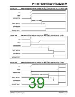
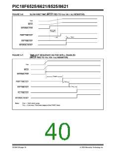
PIC18F6525/6621/8525/8621
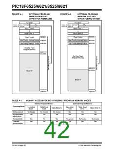
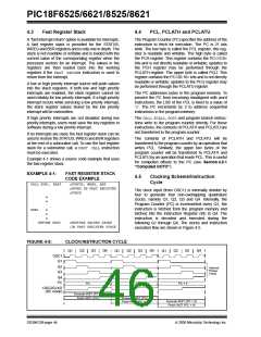
FIGURE 4-1:
INTERNAL PROGRAM
MEMORY MAP AND
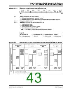
FIGURE 4-2:
INTERNAL PROGRAM
MEMORY MAP AND
STACK FOR PIC18FX525
STACK FOR PIC18FX621
PC<20:0>
PC<20:0>
21
21
CALL,RCALL,RETURN
RETFIE,RETLW
CALL,RCALL,RETURN
RETFIE,RETLW
Stack Level 1
Stack Level 1
•
•
•
•
•
•
Stack Level 31
Reset Vector
Stack Level 31
Reset Vector
000000h
000000h
High Priority Interrupt Vector
Low Priority Interrupt Vector
High Priority Interrupt Vector
Low Priority Interrupt Vector
000008h
000018h
000008h
000018h
On-Chip Flash
Program Memory
00BFFFh
00C000h
On-Chip Flash
Program Memory
00FFFFh
010000h
Read ‘0’
Read ‘0’
1FFFFFh
200000h
1FFFFFh
200000h
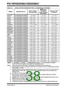
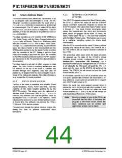
TABLE 4-1:
Operating Mode
Microprocessor
MEMORY ACCESS FOR PIC18F8525/8621 PROGRAM MEMORY MODES
Internal Program Memory
External Program Memory
Execution
From
Table Read
Execution
From
Table Read
From
Table Write To
Table Write To
From
No Access
Yes
No Access
Yes
No Access
Yes
Yes
Yes
Yes
Yes
Yes
Yes
Microprocessor
w/Boot Block
Microcontroller
Yes
Yes
Yes
Yes
Yes
Yes
No Access
Yes
No Access
Yes
No Access
Yes
Extended
Microcontroller
DS39612B-page 40
2005 Microchip Technology Inc.

 MICROCHIP [ MICROCHIP ]