PIC18F6525/6621/8525/8621
If the second word of the instruction is executed by itself
(first word was skipped), it will execute as a NOP. This
action is necessary when the two-word instruction is
preceded by a conditional instruction that changes the
PC. A program example that demonstrates this concept
is shown in Example 4-3. Refer to Section 25.0
“Instruction Set Summary” for further details of the
instruction set.
4.7.1
TWO-WORD INSTRUCTIONS
The PIC18F6525/6621/8525/8621 devices have four
two-word instructions: MOVFF, CALL, GOTOand LFSR.
The second word of these instructions has the 4 MSBs
set to ‘1’s and is a special kind of NOPinstruction. The
lower 12 bits of the second word contain data to be
used by the instruction. If the first word of the instruction
is executed, the data in the second word is accessed.
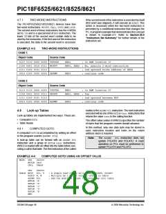
EXAMPLE 4-3:
CASE 1:
TWO-WORD INSTRUCTIONS
Object Code
Source Code
0110 0110 0000 0000 TSTFSZ
1100 0001 0010 0011 MOVFF
1111 0100 0101 0110
REG1
; is RAM location 0?
REG1, REG2 ; No, execute 2-word instruction
; 2nd operand holds address of REG2
0010 0100 0000 0000 ADDWF
REG3
; continue code
CASE 2:
Object Code
Source Code
0110 0110 0000 0000 TSTFSZ
1100 0001 0010 0011 MOVFF
1111 0100 0101 0110
REG1
; is RAM location 0?
REG1, REG2 ; Yes
; 2nd operand becomes NOP
0010 0100 0000 0000 ADDWF
REG3
; continue code
routine is the ADDWFPCLinstruction. The next instruction
executed will be one of the RETLW0xnn instructions that
returns the value 0xnnto the calling function.
4.8
Look-up Tables
Look-up tables are implemented two ways. These are:
• Computed GOTO
The offset value (value in WREG) specifies the number
of bytes that the program counter should advance.
• Table Reads
In this method, only one data byte may be stored in
each instruction location and room on the return
address stack is required.
4.8.1
COMPUTED GOTO
A computed GOTOis accomplished by adding an offset
to the program counter (ADDWF PCL).
Note:
The ADDWF PCL instruction does not
update PCLATH and PCLATU. A read
operation on PCL must be performed to
update PCLATH and PCLATU.
A look-up table can be formed with an ADDWF PCL
instruction and a group of RETLW 0xnn instructions.
WREG is loaded with an offset into the table before exe-
cuting a call to that table. The first instruction of the called
EXAMPLE 4-4:
COMPUTED GOTO USING AN OFFSET VALUE
MAIN: ORG
0x0000
MOVLW 0x00
CALL
TABLE
…
ORG
TABLE MOVF
0x8000
PCL, F
; A simple read of PCL will update PCLATH, PCLATU
; Multiply by 2 to get correct offset in table
; Add the modified offset to force jump into table
RLNCF W, W
ADDWF PCL
RETLW ‘A’
RETLW ‘B’
RETLW ‘C’
RETLW ‘D’
RETLW ‘E’
END
DS39612B-page 46
2005 Microchip Technology Inc.

 MICROCHIP [ MICROCHIP ]