PIC18F6525/6621/8525/8621
TABLE 16-1: CCP MODE – TIMER
RESOURCE
Timer Resource
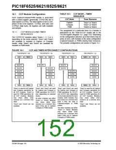
16.1 CCP Module Configuration
Each Capture/Compare/PWM module is associated
with a control register (generically, CCPxCON) and a
data register (CCPRx). The data register in turn is com-
prised of two 8-bit registers: CCPRxL (low byte) and
CCPRxH (high byte). All registers are both readable
and writable.
CCP Mode
Capture
Compare
PWM
Timer1 or Timer3
Timer1 or Timer3
Timer2 or Timer4
The assignment of a particular timer to a module is
determined by the Timer-to-CCP enable bits in the
T3CON register (Register 14-1, page 143). Depending
on the configuration selected, up to four timers may be
active at once, with modules in the same configuration
(Capture/Compare or PWM) sharing timer resources.
The possible configurations are shown in Figure 16-1.
16.1.1
CCP MODULES AND TIMER
RESOURCES
The CCP/ECCP modules utilize Timers 1, 2, 3 or 4,
depending on the mode selected. Timer1 and Timer3
are available to modules in Capture or Compare
modes, while Timer2 and Timer4 are available for
modules in PWM mode.
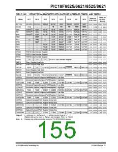
FIGURE 16-1:
CCP AND TIMER INTERCONNECT CONFIGURATIONS
T3CCP<2:1> = 00
T3CCP<2:1> = 01
T3CCP<2:1> = 10
T3CCP<2:1> = 11
TMR1
TMR3
TMR1
TMR3
TMR1
TMR3
TMR1
TMR3
ECCP1
ECCP2
ECCP3
CCP4
ECCP1
ECCP1
ECCP2
ECCP1
ECCP2
ECCP3
CCP4
ECCP2
ECCP3
CCP4
ECCP3
CCP4
CCP5
CCP5
CCP5
CCP5
TMR2
TMR4
TMR2
TMR4
TMR2
TMR4
TMR2
TMR4
Timer1 is used for all Capture Timer1 and Timer2 are used Timer1 and Timer2 are used
for Capture and Compare or
all CCP modules. Timer2 is PWM operations for ECCP1 PWM operations for ECCP1
used for PWM operations for only (depending on selected and ECCP2 only (depending
Timer3 is used for all Capture
and Compare operations for
all CCP modules. Timer4 is
used for PWM operations for
all CCP modules. Modules
may share either timer
resource as a common time
base.
and Compare operations for for Capture and Compare or
on the mode selected for each
module). Both modules may
use a timer as a common time
base if they are both in
Capture/Compare or PWM
modes.
all CCP modules. Modules mode).
may share either timer
All other modules use either
resource as a common time
base.
Timer3 or Timer4. Modules
may share either timer
Timer3 and Timer4 are not resource as a common time
Timer1 and Timer2 are not
available.
available.
base if they are in Capture/
Compare or PWM modes.
The other modules use either
Timer3 or Timer4. Modules
may share either timer
resource as a common time
base if they are in Capture/
Compare or PWM modes.
DS39612B-page 150
2005 Microchip Technology Inc.

 MICROCHIP [ MICROCHIP ]