PIC18F6525/6621/8525/8621
9.4
IPR Registers
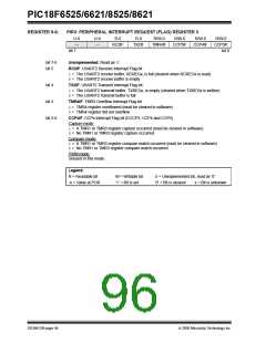
The IPR registers contain the individual priority bits for
the peripheral interrupts. Due to the number of
peripheral interrupt sources, there are three Peripheral
Interrupt Priority registers (IPR1, IPR2 and IPR3). The
operation of the priority bits requires that the Interrupt
Priority Enable (IPEN) bit be set.
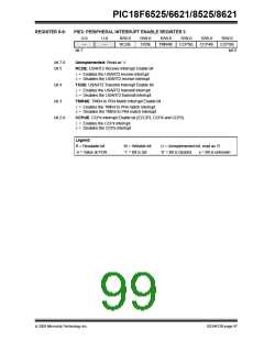
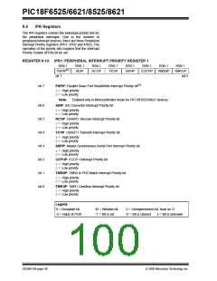
REGISTER 9-10: IPR1: PERIPHERAL INTERRUPT PRIORITY REGISTER 1
R/W-1
PSPIP(1)
bit 7
R/W-1
ADIP
R/W-1
RC1IP
R/W-1
TX1IP
R/W-1
SSPIP
R/W-1
R/W-1
R/W-1
TMR1IP
bit 0
CCP1IP
TMR2IP
bit 7
PSPIP: Parallel Slave Port Read/Write Interrupt Priority bit(1)
1= High priority
0= Low priority
Note:
Enabled only in Microcontroller mode for PIC18F8525/8621 devices.
bit 6
bit 5
bit 4
bit 3
bit 2
bit 1
bit 0
ADIP: A/D Converter Interrupt Priority bit
1= High priority
0= Low priority
RC1IP: USART1 Receive Interrupt Priority bit
1= High priority
0= Low priority
TX1IP: USART1 Transmit Interrupt Priority bit
1= High priority
0= Low priority
SSPIP: Master Synchronous Serial Port Interrupt Priority bit
1= High priority
0= Low priority
CCP1IP: ECCP1 Interrupt Priority bit
1= High priority
0= Low priority
TMR2IP: TMR2 to PR2 Match Interrupt Priority bit
1= High priority
0= Low priority
TMR1IP: TMR1 Overflow Interrupt Priority bit
1= High priority
0= Low priority
Legend:
R = Readable bit
-n = Value at POR
W = Writable bit
‘1’ = Bit is set
U = Unimplemented bit, read as ‘0’
‘0’ = Bit is cleared x = Bit is unknown
DS39612B-page 98
2005 Microchip Technology Inc.

 MICROCHIP [ MICROCHIP ]