PIC18F6525/6621/8525/8621
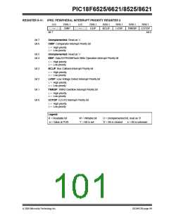
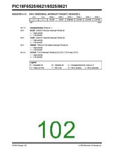
REGISTER 9-12: IPR3: PERIPHERAL INTERRUPT PRIORITY REGISTER 3
U-0
—
U-0
—
R/W-1
RC2IP
R/W-1
TX2IP
R/W-1
R/W-1
R/W-1
R/W-1
TMR4IP
CCP5IP
CCP4IP
CCP3IP
bit 7
bit 0
bit 7-6
bit 5
Unimplemented: Read as ‘0’
RC2IP: USART2 Receive Interrupt Priority bit
1= High priority
0= Low priority
bit 4
TX2IP: USART2 Transmit Interrupt Priority bit
1= High priority
0= Low priority
bit 3
TMR4IP: TMR4 to PR4 Match Interrupt Priority bit
1= High priority
0= Low priority
bit 2-0
CCPxIP: CCPx Interrupt Priority bit (ECCP3, CCP4 and CCP5)
1= High priority
0= Low priority
Legend:
R = Readable bit
-n = Value at POR
W = Writable bit
‘1’ = Bit is set
U = Unimplemented bit, read as ‘0’
‘0’ = Bit is cleared x = Bit is unknown
DS39612B-page 100
2005 Microchip Technology Inc.

 MICROCHIP [ MICROCHIP ]