PIC18F2220/2320/4220/4320
A shutdown event can be caused by either of the two
comparator modules or the INT0 pin (or any combina-
tion of these three sources). The comparators may be
used to monitor a voltage input proportional to a current
being monitored in the bridge circuit. If the voltage
exceeds a threshold, the comparator switches state
and triggers a shutdown. Alternatively, a digital signal
on the INT0 pin can also trigger a shutdown. The auto-
shutdown feature can be disabled by not selecting any
auto-shutdown sources. The auto-shutdown sources to
be used are selected using the ECCPAS2:ECCPAS0
bits (ECCPAS<6:4>).
16.4.4
PROGRAMMABLE DEAD BAND
DELAY
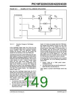
In half-bridge applications, where all power switches
are modulated at the PWM frequency at all times, the
power switches normally require more time to turn off
than to turn on. If both the upper and lower power
switches are switched at the same time (one turned on
and the other turned off), both switches may be on for
a short period of time until one switch completely turns
off. During this brief interval, a very high current (shoot-
through current) may flow through both power
switches, shorting the bridge supply. To avoid this
potentially destructive shoot-through current from flow-
ing during switching, turning on either of the power
switches is normally delayed to allow the other switch
to completely turn off.
When a shutdown occurs, the output pins are asyn-
chronously placed in their shutdown states, specified
by the PSSAC1:PSSAC0 and PSSBD1:PSSBD0 bits
(ECCPAS<3:0>). Each pin pair (P1A/P1C and P1B/
P1D) may be set to drive high, drive low or be tri-stated
(not driving). The ECCPASE bit (ECCPAS<7>) is also
set to hold the enhanced PWM outputs in their
shutdown states.
In the Half-Bridge Output mode, a digitally program-
mable dead band delay is available to avoid shoot-
through current from destroying the bridge power
switches. The delay occurs at the signal transition from
the non-active state to the active state. See Figure 16-4
for illustration. The lower seven bits of the PWM1CON
register (Register 16-2) set the delay period in terms of
microcontroller instruction cycles (TCY or 4 TOSC).
The ECCPASE bit is set by hardware when a shutdown
event occurs. If automatic restarts are not enabled, the
ECCPASE bit is cleared by firmware when the cause of
the shutdown clears. If automatic restarts are enabled,
the ECCPASE bit is automatically cleared when the
cause of the auto-shutdown has cleared.
16.4.5
ENHANCED PWM
AUTO-SHUTDOWN
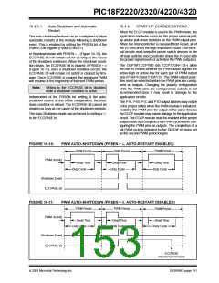
If the ECCPASE bit is set when a PWM period begins,
the PWM outputs remain in their shutdown state for that
entire PWM period. When the ECCPASE bit is cleared,
the PWM outputs will return to normal operation at the
beginning of the next PWM period.
When the ECCP is programmed for any of the
enhanced PWM modes, the active output pins may be
configured for auto-shutdown. Auto-shutdown immedi-
ately places the enhanced PWM output pins into a
defined shutdown state when a shutdown event
occurs.
Note:
Writing to the ECCPASE bit is disabled
while a shutdown condition is active.
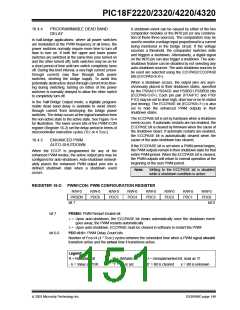
REGISTER 16-2: PWM1CON: PWM CONFIGURATION REGISTER
R/W-0
R/W-0
PDC6
R/W-0
PDC5
R/W-0
PDC4
R/W-0
PDC3
R/W-0
PDC2
R/W-0
PDC1
R/W-0
PDC0
PRSEN
bit 7
bit 0
bit 7
PRSEN: PWM Restart Enable bit
1= Upon auto-shutdown, the ECCPASE bit clears automatically once the shutdown event
goes away; the PWM restarts automatically
0= Upon auto-shutdown, ECCPASE must be cleared in software to restart the PWM
bit 6-0
PDC<6:0>: PWM Delay Count bits
Number of FOSC/4 (4 * TOSC) cycles between the scheduled time when a PWM signal should
transition active and the actual time it transitions active.
Legend:
R = Readable bit
W = Writable bit
‘1’ = Bit is set
U = Unimplemented bit, read as ‘0’
‘0’ = Bit is cleared x = Bit is unknown
- n = Value at POR
2003 Microchip Technology Inc.
DS39599C-page 149

 MICROCHIP [ MICROCHIP ]