PIC17C75X
2
External pull-up resistors are used to ensure a high
level when no device is pulling the line down.The num-
ber of devices that may be attached to the I C bus is
limited only by the maximum bus loading specification
of 400 pF.
APPENDIX E: I C OVERVIEW
This section provides an overview of the Inter-Inte-
grated Circuit (I C) bus, with Section 15.2 discussing
the operation of the SSP module in I C mode.
2
2
2
2
The I C bus is a two-wire serial interface developed by
E.1
Initiating and Terminating Data
Transfer
the Philips Corporation. The original specification, or
standard mode, was for data transfers of up to 100
Kbps. This device will communicate with fast mode
devices if attached to the same bus.
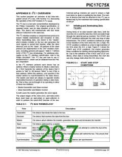
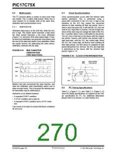
During times of no data transfer (idle time), both the
clock line (SCL) and the data line (SDA) are pulled high
through the external pull-up resistors. The START and
STOP conditions determine the start and stop of data
transmission.The START condition is defined as a high
to low transition of the SDA when the SCL is high. The
STOP condition is defined as a low to high transition of
the SDA when the SCL is high. Figure E-1 shows the
START and STOP conditions. The master generates
these conditions for starting and terminating data trans-
fer. Due to the definition of the START and STOP con-
ditions, when data is being transmitted, the SDA line
can only change state when the SCL line is low.
2
The I C interface employs a comprehensive protocol to
ensure reliable transmission and reception of data.
When transmitting data, one device is the “master”
which initiates transfer on the bus and generates the
clock signals to permit that transfer, while the other
device(s) acts as the “slave.” All portions of the slave
protocol are implemented in the SSP module’s hard-
ware, including general call support. Table E-1 defines
some of the I C bus terminology. For additional infor-
mation on the I C interface specification, refer to the
Philips document “The I C bus and how to use it.”
#939839340011, which can be obtained from the Phil-
ips Corporation.
2
2
2
FIGURE E-1: START AND STOP
CONDITIONS
2
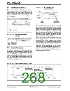
In the I C interface protocol each device has an
address.When a master wishes to initiate a data trans-
fer, it first transmits the address of the device that it
wishes to “talk” to. All devices “listen” to see if this is
their address. Within this address, a bit specifies if the
master wishes to read-from/write-to the slave device.
The master and slave are always in opposite modes
(transmitter/receiver) of operation during a data trans-
fer.That is they can be thought of as operating in either
of these two relations:
SDA
S
SCL
P
Change
of Data
Allowed
Change
of Data
Allowed
Start
Stop
Condition
Condition
• Master-transmitter and Slave-receiver
• Slave-transmitter and Master-receiver
In both cases the master generates the clock signal.
The output stages of the clock (SCL) and data (SDA)
lines must have an open-drain or open-collector in
order to perform the wired-AND function of the bus.
2
TABLE E-1:
Term
I C BUS TERMINOLOGY
Description
Transmitter
Receiver
Master
The device that sends the data to the bus.
The device that receives the data from the bus.
The device which initiates the transfer, generates the clock and terminates the transfer.
The device addressed by a master.
Slave
Multi-master
More than one master device in a system. These masters can attempt to control the bus at the
same time without corrupting the message.
Arbitration
Procedure that ensures that only one of the master devices will control the bus. This ensure that
the transfer data does not get corrupted.
Synchronization
Procedure where the clock signals of two or more devices are synchronized.
1997 Microchip Technology Inc.
Preliminary
DS30264A-page 267

 MICROCHIP [ MICROCHIP ]