PIC17C75X
17.1
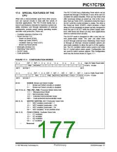
Configuration Bits
17.2
Oscillator Configurations
The PIC17CXXX has eight configuration locations
(Table 17-1). These locations can be programmed
(read as '0') or left unprogrammed (read as '1') to select
various device configurations. Any write to a configura-
tion location, regardless of the data, will program that
configuration bit. A TABLWT instruction is required to
write to program memory locations. The configuration
bits can be read by using the TABLRD instructions.
Reading any configuration location between FE00h
and FE07h will read the low byte of the configuration
word (Figure 17-1) into the TABLATL register.The TAB-
LATH register will be FFh. Reading a configuration
location between FE08h and FE0Fh will read the high
byte of the configuration word into the TABLATL regis-
ter. The TABLATH register will be FFh.
17.2.1 OSCILLATOR TYPES
The PIC17CXXX can be operated in four different oscil-
lator modes. The user can program two configuration
bits (FOSC1:FOSC0) to select one of these four
modes:
• LF
• XT
• EC
• RC
Low Power Crystal
Crystal/Resonator
External Clock Input
Resistor/Capacitor
For information on the different oscillator types and
how to use them, please refer to Section 4.0.
Addresses FE00h thorough FE0Fh are only in the pro-
gram memory space for microcontroller and code pro-
tected microcontroller modes. A device programmer
will be able to read the configuration word in any pro-
cessor mode. See programming specifications for
more detail.
TABLE 17-1: CONFIGURATION
LOCATIONS
Bit
Address
FOSC0
FOSC1
WDTPS0
WDTPS1
PM0
FE00h
FE01h
FE02h
FE03h
FE04h
FE06h
FE0Eh
FE0Fh
PM1
BODEN
PM2
Note: When programming the desired configura-
tion locations, they must be programmed
in ascending order. Starting with address
FE00h.
DS30264A-page 178
Preliminary
1997 Microchip Technology Inc.

 MICROCHIP [ MICROCHIP ]