PIC17C75X
The PIC17CXXX has a Watchdog Timer which can be
shutoff only through EPROM bits. It runs off its own RC
oscillator for added reliability. There are two timers that
offer necessary delays on power-up. One is the Oscil-
lator Start-up Timer (OST), intended to keep the chip in
RESET until the crystal oscillator is stable.The other is
the Power-up Timer (PWRT), which provides a fixed
delay of 96 ms (nominal) on power-up only, designed to
keep the part in RESET while the power supply stabi-
lizes. With these two timers on-chip, most applications
need no external reset circuitry.
17.0 SPECIAL FEATURES OF THE
CPU
What sets a microcontroller apart from other proces-
sors are special circuits to deal with the needs of
real-time applications. The PIC17CXXX family has a
host of such features intended to maximize system reli-
ability, minimize cost through elimination of external
components, provide power saving operating modes
and offer code protection. These are:
• Oscillator selection (Section 4.0)
• Reset (Section 5.0)
The SLEEP mode is designed to offer a very low cur-
rent power-down mode. The user can wake from
SLEEP through external reset, Watchdog Timer Reset
or through an interrupt. Several oscillator options are
also made available to allow the part to fit the applica-
tion. The RC oscillator option saves system cost while
the LF crystal option saves power. Configuration bits
are used to select various options. This configuration
word has the format shown in Figure 17-1.
- Power-on Reset (POR)
- Power-up Timer (PWRT)
- Oscillator Start-up Timer (OST)
- Brown-out Reset (BOR)
• Interrupts (Section 6.0)
• Watchdog Timer (WDT)
• SLEEP mode
• Code protection
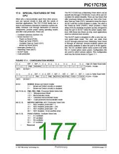
FIGURE 17-1: CONFIGURATION WORDS
U - x
bit15
U - x
bit15
bit 6H
R/P - 1 R/P - 1 U - x U - x
PM2 BODEN
bit 8 bit 7
U - x
—
U - x
—
U - x
—
U - x
—
High (H) Table Read Addr.
FE0Fh - FE08h
—
—
—
bit 0
U - x
R/P - 1 U - x R/P - 1 R/P - 1
R/P - 1
R/P - 1 R/P - 1 Low (L) Table Read Addr.
—
—
PM1
—
PM0 WDTPS1 WDTPS0 FOSC1 FOSC0 FE07h - FE00h
bit 0
bit 8 bit 7
BODEN: Brown-out Detect Enable
1 =
0 =
Brown-out Detect circuitry is enabled
Brown-out Detect circuitry is disabled
bits 7H:6L:4L PM2, PM1, PM0, Processor Mode Select bits
111 = Microprocessor Mode
110 = Microcontroller mode
101 = Extended microcontroller mode
000 = Code protected microcontroller mode
bits 2L:3L
bits 1L:0L
—
WDTPS1:WDTPS0, WDT Postscaler Select bits
11 = WDT enabled, postscaler = 1
10 = WDT enabled, postscaler = 256
01 = WDT enabled, postscaler = 64
00 = WDT disabled, 16-bit overflow timer
FOSC1:FOSC0, Oscillator Select bits
11 = EC oscillator
10 = XT oscillator
01 = RC oscillator
00 = LF oscillator
Reserved
1997 Microchip Technology Inc.
Preliminary
DS30264A-page 177

 MICROCHIP [ MICROCHIP ]