PIC17C75X
4.1.2
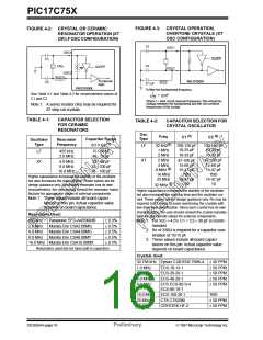
CRYSTAL OSCILLATOR / CERAMIC
RESONATORS
4.0
ON-CHIP OSCILLATOR
CIRCUIT
In XT or LF modes, a crystal or ceramic resonator is
connected to the OSC1/CLKIN and OSC2/CLKOUT
pins to establish oscillation (Figure 4-2). The
PIC17CXXX oscillator design requires the use of a par-
allel cut crystal. Use of a series cut crystal may give a
frequency out of the crystal manufacturers specifica-
tions.
The internal oscillator circuit is used to generate the
device clock. Four device clock periods generate an
internal instruction clock (TCY). There are four modes
that the oscillator can operate in.These are selected by
the device configuration bits during device program-
ming. These modes are:
• LF
• XT
Low Frequency (FOSC <= 2 MHz)
For frequencies above 20 MHz, it is common for the
crystal to be an overtone mode crystal. Use of overtone
mode crystals require a tank circuit to attenuate the
gain at the fundamental frequency. Figure 4-3 shows
an example circuit.
Standard Crystal/Resonator Frequency
(2 MHz <= FOSC <= 33 MHz)
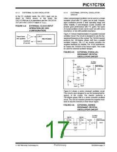
• EC
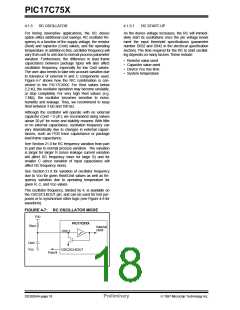
• RC
External Clock Input
(Default oscillator configuration)
External Resistor/Capacitor
(FOSC <= 4 MHz)
4.1.2.1
OSCILLATOR / RESONATOR START-UP
There are two timers that offer necessary delays on
power-up. One is the Oscillator Start-up Timer (OST),
intended to keep the chip in RESET until the crystal
oscillator is stable. The other is the Power-up Timer
(PWRT), which provides a fixed delay of 96 ms (nomi-
nal) on power-up only, designed to keep the part in
RESET while the power supply stabilizes. With these
two timers on-chip, most applications need no external
reset circuitry.
As the device voltage increases from Vss, the oscillator
will start its oscillations. The time required for the oscil-
lator to start oscillating depends on many factors.
These include:
• Crystal / resonator frequency
• Capacitor values used (C1 and C2)
• Device VDD rise time.
• System temperature
• Series resistor value (and type) if used
• Oscillator mode selection of device (which selects
the gain of the internal oscillator inverter)
SLEEP mode is designed to offer a very low current
power-down mode. The user can wake from SLEEP
through external reset, Watchdog Timer Reset or
through an interrupt.
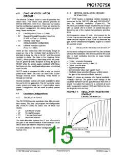
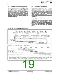
Figure 4-1 shows an example of a typical oscillator /
resonator start-up. The peak-to-peak voltage of the
oscillator waveform can be quite low (less than 50% of
device VDD) when the waveform is centered at VDD/2
(refer to parameter number D033 and D043 in the elec-
trical specification section).
Several oscillator options are made available to allow
the part to fit the application. The RC oscillator option
saves system cost while the LF crystal option saves
power. Configuration bits are used to select various
options.
FIGURE 4-1: OSCILLATOR / RESONATOR
START-UP
4.1
Oscillator Configurations
CHARACTERISTICS
4.1.1
OSCILLATOR TYPES
The PIC17CXXX can be operated in four different oscil-
lator modes. The user can program two configuration
bits (FOSC1:FOSC0) to select one of these four
modes:
• LF
• XT
• EC
• RC
Low Power Crystal
Crystal/Resonator
External Clock Input
Resistor/Capacitor
The main difference between the LF and XT modes is
the gain of the internal inverter of the oscillator circuit
which allows the different frequency ranges.
For more details on the device configuration bits, see
Section 17.0.
Crystal Start-up Time
Time
1997 Microchip Technology Inc.
Preliminary
DS30264A-page 15

 MICROCHIP [ MICROCHIP ]