PIC17C75X
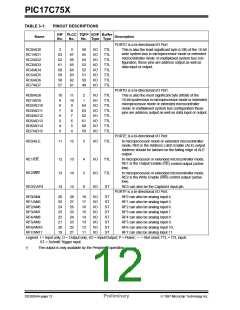
TABLE 3-1:
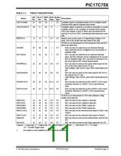
PINOUT DESCRIPTIONS
DIP PLCC TQFP I/O/P Buffer
Name
Description
No.
No.
No. Type Type
PORTC is a bi-directional I/O Port.
RC0/AD0
RC1/AD1
RC2/AD2
RC3/AD3
RC4/AD4
RC5/AD5
RC6/AD6
RC7/AD7
2
3
58
55
54
53
52
51
50
49
I/O
I/O
I/O
I/O
I/O
I/O
I/O
I/O
TTL
TTL
TTL
TTL
TTL
TTL
TTL
TTL
This is also the least significant byte (LSB) of the 16-bit
wide system bus in microprocessor mode or extended
microcontroller mode. In multiplexed system bus con-
figuration, these pins are address output as well as
data input or output.
63
62
61
60
58
58
57
67
66
65
64
63
62
61
PORTD is a bi-directional I/O Port.
RD0/AD8
RD1/AD9
RD2/AD10
RD3/AD11
RD4/AD12
RD5/AD13
RD6/AD14
RD7/AD15
10
9
11
10
9
2
I/O
I/O
I/O
I/O
I/O
I/O
I/O
I/O
TTL
TTL
TTL
TTL
TTL
TTL
TTL
TTL
This is also the most significant byte (MSB) of the
16-bit system bus in microprocessor mode or extended
microprocessor mode or extended microcontroller
mode. In multiplexed system bus configuration these
pins are address output as well as data input or output.
1
8
64
63
62
61
60
59
7
8
6
7
5
6
4
5
3
4
PORTE is a bi-directional I/O Port.
RE0/ALE
11
12
3
I/O
TTL
In microprocessor mode or extended microcontroller
mode, RE0 is the Address Latch Enable (ALE) output.
Address should be latched on the falling edge of ALE
output.
RE1/OE
12
13
14
13
14
15
4
5
6
I/O
I/O
I/O
TTL
TTL
ST
In microprocessor or extended microcontroller mode,
RE1 is the Output Enable (OE) control output (active
low).
RE2/WR
RE3/CAP4
In microprocessor or extended microcontroller mode,
RE2 is the Write Enable (WR) control output (active
low).
RE3 can also be the Capture4 input pin.
PORTF is a bi-directional I/O Port.
RF0 can also be analog input 4.
RF1 can also be analog input 5.
RF2 can also be analog input 6.
RF3 can also be analog input 7.
RF4 can also be analog input 8.
RF5 can also be analog input 9.
RF6 can also be analog input 10.
RF7 can slso be analog input 11.
RF0/AN4
RF1/AN5
RF2/AN6
RF3/AN7
RF4/AN8
RF5/AN9
RF6/AN10
RF7/AN11
26
25
24
23
22
21
20
19
28
27
26
25
24
23
22
21
18
17
16
15
14
13
12
11
I/O
I/O
I/O
I/O
I/O
I/O
I/O
I/O
ST
ST
ST
ST
ST
ST
ST
ST
Legend: I = Input only; O = Output only; I/O = Input/Output; P = Power; — = Not Used; TTL = TTL input;
ST = Schmitt Trigger input.
†
The output is only available by the Peripheral operation.
DS30264A-page 12
Preliminary
1997 Microchip Technology Inc.

 MICROCHIP [ MICROCHIP ]