PIC17C75X
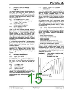
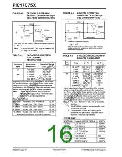
FIGURE 4-3: CRYSTAL OPERATION,
OVERTONE CRYSTALS (XT
OSC CONFIGURATION)
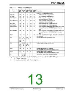
FIGURE 4-2: CRYSTAL OR CERAMIC
RESONATOR OPERATION (XT
ORLFOSCCONFIGURATION)
C1
OSC1
OSC1
SLEEP
C1
C2
XTAL
SLEEP
RF
OSC2
OSC2
Note1
To internal
logic
PIC17CXXX
C2
0.1 µF
PIC17CXXX
To filter the fundamental frequency
1
See Table 4-1 and Table 4-2 for recommended values of
C1 and C2.
(2πf)2
=
LC2
Where f = tank circuit resonant frequency. This should be
midway between the fundamental and the 3rd overtone
frequencies of the crystal.
Note 1: A series resistor (Rs) may be required for
AT strip cut crystals.
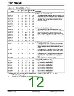
TABLE 4-1:
CAPACITOR SELECTION
FOR CERAMIC
RESONATORS
TABLE 4-2:
CAPACITOR SELECTION FOR
CRYSTAL OSCILLATOR
Osc
Type
(3)
(3)
Freq
C1
C2
Capacitor Range
Oscillator
Type
Resonator
Frequency
(1)
(1)
C1 = C2
LF
32 kHz
100-150 pF
10-33 pF
10-33 pF
100-150 pF
10-33 pF
10-33 pF
1 MHz
2 MHz
LF
455 kHz
2.0 MHz
15 - 68 pF
10 - 33 pF
XT
2 MHz
4 MHz
8 MHz
16 MHz
25 MHz
47-100 pF
15-68 pF
15-47 pF
TBD
15-47 pF
10
47-100 pF
15-68 pF
15-47 pF
TBD
15-47 pF
10
XT
4.0 MHz
8.0 MHz
16.0 MHz
22 - 68 pF
33 - 100 pF
33 - 100 pF
(2)
Higher capacitance increases the stability of the oscillator
but also increases the start-up time. These values are for
design guidance only. Since each resonator has its own
characteristics, the user should consult the resonator manu-
facturer for appropriate values of external components.
Note 1: These values include all board capaci-
tances on this pin. Actual capacitor value
(3)
32 MHz
Higher capacitance increases the stability of the oscillator
but also increases the start-up time and the oscillator cur-
rent. These values are for design guidance only. RS may be
required in XT mode to avoid overdriving the crystals with
low drive level specification. Since each crystal has its own
characteristics, the user should consult the crystal manufac-
turer for appropriate values for external components.
Note 1: For VDD > 4.5V, C1 = C2 ≈ 30 pF is recom-
mended.
depends on board capacitance
Resonators Used:
455 kHz
2.0 MHz
4.0 MHz
8.0 MHz
Panasonic EFO-A455K04B
Murata Erie CSA2.00MG
Murata Erie CSA4.00MG
Murata Erie CSA8.00MT
± 0.3%
± 0.5%
± 0.5%
± 0.5%
± 0.5%
2: RS of 330Ω is required for a capacitor com-
bination of 15/15 pF.
3: These values include all board capaci-
tances on this pin. Actual capacitor value
depends on board capacitance
16.0 MHz Murata Erie CSA16.00MX
Resonators used did not have built-in capacitors.
Crystals Used:
32.768 kHz Epson C-001R32.768K-A ± 20 PPM
1.0 MHz
2.0 MHz
4.0 MHz
8.0 MHz
ECS-10-13-1
ECS-20-20-1
ECS-40-20-1
± 50 PPM
± 50 PPM
± 50 PPM
± 50 PPM
ECS ECS-80-S-4
ECS-80-18-1
16.0 MHz
25 MHz
32 MHz
ECS-160-20-1
CTS CTS25M
CRYSTEK HF-2
TBD
± 50 PPM
± 50 PPM
DS30264A-page 16
Preliminary
1997 Microchip Technology Inc.

 MICROCHIP [ MICROCHIP ]