PIC17C75X
4.1.3
EXTERNAL CLOCK OSCILLATOR
4.1.4
EXTERNAL CRYSTAL OSCILLATOR
CIRCUIT
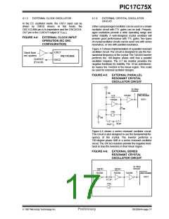
In the EC oscillator mode, the OSC1 input can be
driven by CMOS drivers. In this mode, the
OSC1/CLKIN pin is hi-impedance and the OSC2/CLK-
OUT pin is the CLKOUT output (4 TOSC).
Either a prepackaged oscillator can be used or a simple
oscillator circuit with TTL gates can be built. Prepack-
aged oscillators provide a wide operating range and
better stability. A well-designed crystal oscillator will
provide good performance with TTL gates. Two types
of crystal oscillator circuits can be used: one with series
resonance, or one with parallel resonance.
FIGURE 4-4: EXTERNAL CLOCK INPUT
OPERATION (EC OSC
CONFIGURATION)
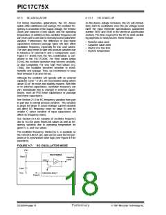
Figure 4-5 shows implementation of a parallel resonant
oscillator circuit. The circuit is designed to use the fun-
damental frequency of the crystal.The 74AS04 inverter
performs the 180-degree phase shift that a parallel
oscillator requires. The 4.7 kΩ resistor provides the
negative feedback for stability. The 10 kΩ potentiome-
ter biases the 74AS04 in the linear region. This could
be used for external oscillator designs.
OSC1
OSC2
Clock from
ext. system
PIC17CXXX
CLKOUT
(FOSC/4)
FIGURE 4-5: EXTERNAL PARALLEL
RESONANT CRYSTAL
OSCILLATOR CIRCUIT
+5V
To Other
Devices
10k
74AS04
PIC17CXXX
4.7k
OSC1
74AS04
10k
XTAL
10k
20 pF
20 pF
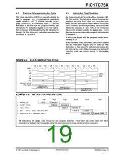
Figure 4-6 shows a series resonant oscillator circuit.
This circuit is also designed to use the fundamental fre-
quency of the crystal. The inverter performs a
180-degree phase shift in a series resonant oscillator
circuit. The 330 kΩ resistors provide the negative feed-
back to bias the inverters in their linear region.
FIGURE 4-6: EXTERNAL SERIES
RESONANT CRYSTAL
OSCILLATOR CIRCUIT
To Other
Devices
330 kΩ
330 kΩ
74AS04
74AS04
74AS04
PIC17CXXX
OSC1
0.1 µF
XTAL
1997 Microchip Technology Inc.
Preliminary
DS30264A-page 17

 MICROCHIP [ MICROCHIP ]