PIC16F913/914/916/917/946
They are not affected by a WDT wake-up since this is
viewed as the resumption of normal operation. TO and
16.2 Resets
The PIC16F91X/946 differentiates between various
kinds of Reset:
PD bits are set or cleared differently in different Reset
situations, as indicated in Table 16-2. These bits are
used in software to determine the nature of the Reset.
See Table 16-5 for a full description of Reset states of
all registers.
a) Power-on Reset (POR)
b) WDT Reset during normal operation
c) WDT Reset during Sleep
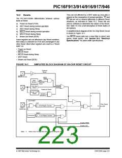
A simplified block diagram of the On-Chip Reset Circuit
is shown in Figure 16-1.
d) MCLR Reset during normal operation
e) MCLR Reset during Sleep
f) Brown-out Reset (BOR)
The MCLR Reset path has a noise filter to detect and
ignore small pulses. See Section 19.0 “Electrical
Specifications” for pulse width specifications.
Some registers are not affected in any Reset condition;
their status is unknown on POR and unchanged in any
other Reset. Most other registers are reset to a “Reset
state” on:
• Power-on Reset
• MCLR Reset
• MCLR Reset during Sleep
• WDT Reset
• Brown-out Reset (BOR)
FIGURE 16-1:
SIMPLIFIED BLOCK DIAGRAM OF ON-CHIP RESET CIRCUIT
External
Reset
MCLR/VPP pin
Sleep
WDT
WDT
Module
Time-out
Reset
VDD Rise
Detect
Power-on Reset
VDD
Brown-out(1)
Reset
BOREN
SBOREN
S
OST/PWRT
OST
10-bit Ripple Counter
Chip_Reset
R
Q
OSC1/
CLKIN pin
PWRT
11-bit Ripple Counter
LFINTOSC
Enable PWRT
Enable OST
Note 1: Refer to the Configuration Word register (Register 16-1).
© 2007 Microchip Technology Inc.
DS41250F-page 221

 MICROCHIP [ MICROCHIP ]