PIC16F913/914/916/917/946
If VDD drops below VBOR while the Power-up Timer is
running, the chip will go back into a Brown-out Reset
and the Power-up Timer will be re-initialized. Once VDD
rises above VBOR, the Power-up Timer will execute a
64 ms Reset.
16.2.4
BROWN-OUT RESET (BOR)
The BOREN0 and BOREN1 bits in the Configuration
Word register selects one of four BOR modes. Two
modes have been added to allow software or hardware
control of the BOR enable. When BOREN<1:0> = 01,
the SBOREN bit of the PCON register enables/disables
the BOR allowing it to be controlled in software. By
selecting BOREN<1:0>, the BOR is automatically dis-
abled in Sleep to conserve power and enabled on
wake-up. In this mode, the SBOREN bit is disabled.
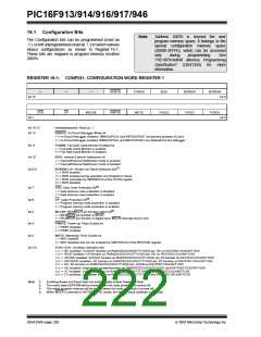
See Register 16-1 for the Configuration Word defini-
tion.
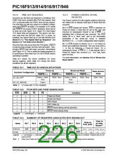
16.2.5
BOR CALIBRATION
The PIC16F91X/946 stores the BOR calibration values
in fuses located in the Calibration Word (2008h). The
Calibration Word is not erased when using the
specified bulk erase sequence in the “PIC16F91X/946
Memory Programming Specification” (DS41244) and
thus, does not require reprogramming.
If VDD falls below VBOR for greater than parameter
(TBOR) (see Section 19.0 “Electrical Specifica-
tions”), the Brown-out situation will reset the device.
This will occur regardless of VDD slew rate. A Reset is
not insured to occur if VDD falls below VBOR for less
than parameter (TBOR).
Address 2008h is beyond the user program memory
space. It belongs to the special configuration memory
space (2000h-3FFFh), which can be accessed only
during programming. See “PIC16F91X/946 Memory
Programming Specification” (DS41244) for more
information.
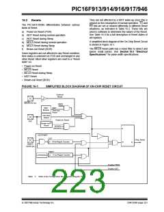
On any Reset (Power-on, Brown-out Reset, Watchdog
Timer, etc.), the chip will remain in Reset until VDD rises
above VBOR (see Figure 16-3). The Power-up Timer
will now be invoked, if enabled and will keep the chip in
Reset an additional 64 ms.
Note:
The Power-up Timer is enabled by the
PWRTE bit in the Configuration Word.
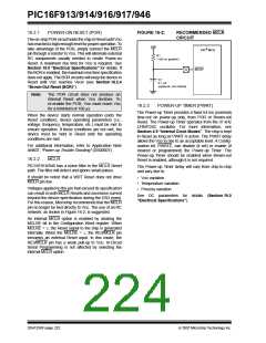
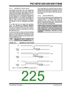
FIGURE 16-3:
BROWN-OUT SITUATIONS
VDD
VBOR
Internal
Reset
(1)
64 ms
VDD
VBOR
Internal
Reset
< 64 ms
(1)
64 ms
VDD
VBOR
Internal
Reset
(1)
64 ms
Note 1: 64 ms delay only if PWRTE bit is programmed to ‘0’.
© 2007 Microchip Technology Inc.
DS41250F-page 223

 MICROCHIP [ MICROCHIP ]