PIC16F688
6.1
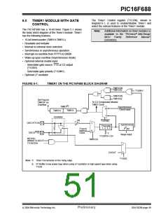
Timer1 Modes of Operation
6.3
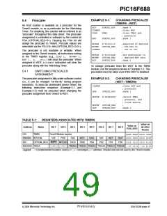
Timer1 Prescaler
Timer1 can operate in one of three modes:
Timer1 has four prescaler options allowing 1, 2, 4 or 8
divisions of the clock input. The T1CKPS bits
(T1CON<5:4>) control the prescale counter. The
prescale counter is not directly readable or writable;
however, the prescaler counter is cleared upon a write
to TMR1H or TMR1L.
• 16-bit timer with prescaler
• 16-bit synchronous counter
• 16-bit asynchronous counter
In Timer mode, Timer1 is incremented on every instruc-
tion cycle. In Counter mode, Timer1 is incremented on
the rising edge of the external clock input T1CKI. In
addition, the Counter mode clock can be synchronized
to the microcontroller system clock or run
asynchronously.
6.4
Timer1 Gate
Timer1 gate source is software configurable to be the
T1G pin or the output of Comparator 2. This allows the
device to directly time external events using T1G or
analog events using Comparator 2. See CMCON1
(Register 7-2) for selecting the Timer1 gate source.
This feature can simplify the software for a Delta-Sigma
A/D converter and many other applications. For more
information on Delta-Sigma A/D converters, see the
Microchip web site (www.microchip.com).
In Counter and Timer modules, the counter/timer clock
can be gated by the Timer1 gate, which can be
selected as either the T1G pin or Comparator 2 output.
If an external clock oscillator is needed (and the
microcontroller is using the INTOSC without CLKOUT),
Timer1 can use the LP oscillator as a clock source.
Note:
TMR1GE bit (T1CON<6>) must be set to
use either T1G or C2OUT as the Timer1
gate source. See Register 7-2 for more
information on selecting the Timer1 gate
source.
Note:
In Counter mode, a falling edge must be
registered by the counter prior to the first
incrementing rising edge.
6.2
Timer1 Interrupt
Timer1 gate can be inverted using the T1GINV bit
(T1CON<7>), whether it originates from the T1G pin or
Comparator 2 output. This configures Timer1 to
measure either the active-high or active-low time
between events.
The Timer1 register pair (TMR1H:TMR1L) increments
to FFFFh and rolls over to 0000h. When Timer1 rolls
over, the Timer1 interrupt flag bit (PIR1<0>) is set. To
enable the interrupt on rollover, you must set these bits:
• Timer1 Interrupt Enable bit (PIE1<0>)
• PEIE bit (INTCON<6>)
• GIE bit (INTCON<7>)
The interrupt is cleared by clearing the TMR1IF bit in
the Interrupt Service Routine.
Note:
The TMR1H:TTMR1L register pair and the
TMR1IF bit should be cleared before
enabling interrupts.
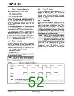
FIGURE 6-2:
TIMER1 INCREMENTING EDGE
T1CKI = 1
when TMR1
Enabled
T1CKI = 0
when TMR1
Enabled
Note 1: Arrows indicate counter increments.
2: In Counter mode, a falling edge must be registered by the counter prior to the first incrementing rising edge of
the clock.
DS41203B-page 50
Preliminary
2004 Microchip Technology Inc.

 MICROCHIP [ MICROCHIP ]