PIC16F/LF1946/47
If two words are written to the TXxREG and then the
SLEEPinstruction is executed, the following will occur:
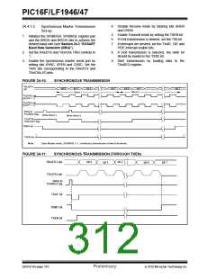
24.4.2
SYNCHRONOUS SLAVE MODE
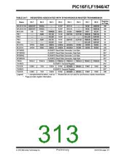
The following bits are used to configure the EUSART
for Synchronous slave operation:
1. The first character will immediately transfer to
the TSR register and transmit.
• SYNC = 1
2. The second word will remain in TXxREG
register.
• CSRC = 0
• SREN = 0(for transmit); SREN = 1(for receive)
• CREN = 0(for transmit); CREN = 1(for receive)
• SPEN = 1
3. The TXxIF bit will not be set.
4. After the first character has been shifted out of
TSR, the TXxREG register will transfer the
second character to the TSR and the TXxIF bit
will now be set.
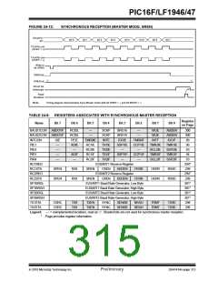
Setting the SYNC bit of the TXxSTA register configures
the device for synchronous operation. Clearing the
CSRC bit of the TXxSTA register configures the device as
a slave. Clearing the SREN and CREN bits of the
RCxSTA register ensures that the device is in the
Transmit mode, otherwise the device will be configured to
receive. Setting the SPEN bit of the RCxSTA register
enables the EUSART. If the RXx/DTx or TXx/CKx pins
are shared with an analog peripheral the analog I/O
functions must be disabled by clearing the corresponding
ANSEL bits.
5. If the PEIE and TXxIE bits are set, the interrupt
will wake the device from Sleep and execute the
next instruction. If the GIE bit is also set, the
program will call the Interrupt Service Routine.
24.4.2.2
Synchronous Slave Transmission
Set-up:
1. Set the SYNC and SPEN bits and clear the
CSRC bit.
RXx/DTx and TXx/CKx pin output drivers must be
disabled by setting the corresponding TRIS bits.
2. Set the RXx/DTx and TXx/CKx TRIS controls to
‘1’.
3. Clear the CREN and SREN bits.
24.4.2.1
EUSART Synchronous Slave
Transmit
4. If using interrupts, ensure that the GIE and PEIE
bits of the INTCON register are set and set the
TXxIE bit.
The operation of the Synchronous Master and Slave
modes are identical (see Section 24.4.1.3
“Synchronous Master Transmission”), except in the
5. If 9-bit transmission is desired, set the TX9 bit.
6. Enable transmission by setting the TXEN bit.
case of the Sleep mode.
7. If 9-bit transmission is selected, insert the Most
Significant bit into the TX9D bit.
8. Start transmission by writing the Least
Significant 8 bits to the TXxREG register.
DS41414A-page 314
Preliminary
2010 Microchip Technology Inc.

 MICROCHIP [ MICROCHIP ]