PIC16F/LF1946/47
4. Disable Receive mode by clearing bits SREN
and CREN.
24.4.1.5
Synchronous Master Transmission
Set-up:
5. Enable Transmit mode by setting the TXEN bit.
6. If 9-bit transmission is desired, set the TX9 bit.
1. Initialize the SPxBRGH, SPxBRGL register pair
and the BRGH and BRG16 bits to achieve the
desired baud rate (see Section 24.3 “EUSART
Baud Rate Generator (BRG)”).
7. If interrupts are desired, set the TXxIE, GIE and
PEIE interrupt enable bits.
2. Set the RXx/DTx and TXx/CKx TRIS controls to
8. If 9-bit transmission is selected, the ninth bit
should be loaded in the TX9D bit.
‘1’.
3. Enable the synchronous master serial port by
setting bits SYNC, SPEN and CSRC. Set the
TRIS bits corresponding to the RXx/DTx and
TXx/CKx I/O pins.
9. Start transmission by loading data to the
TXxREG register.
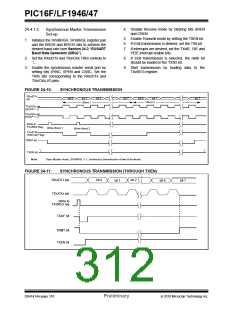
FIGURE 24-10:
SYNCHRONOUS TRANSMISSION
RXx/DTx
pin
bit 0
bit 1
bit 2
bit 7
bit 0
bit 1
Word 2
bit 7
Word 1
TXx/CKx pin
(SCKP = 0)
TXx/CKx pin
(SCKP = 1)
Write to
TXxREG Reg
Write Word 1
Write Word 2
TXxIF bit
(Interrupt Flag)
TRMT bit
‘1’
‘1’
TXEN bit
Note:
Sync Master mode, SPxBRGL = 0, continuous transmission of two 8-bit words.
FIGURE 24-11:
SYNCHRONOUS TRANSMISSION (THROUGH TXEN)
RXx/DTx pin
bit 0
bit 2
bit 1
bit 6
bit 7
TXx/CKx pin
Write to
TXxREG reg
TXxIF bit
TRMT bit
TXEN bit
DS41414A-page 310
Preliminary
2010 Microchip Technology Inc.

 MICROCHIP [ MICROCHIP ]