PIC16F/LF1946/47
25.0 CAPACITIVE SENSING
MODULE
The capacitive sensing module allows for an interaction
with an end user without a mechanical interface. In a
typical application, the capacitive sensing module is
attached to a pad on a Printed Circuit Board (PCB),
which is electrically isolated from the end user. When the
end user places their finger over the PCB pad, a
capacitive load is added, causing a frequency shift in the
capacitive sensing module. The capacitive sensing
module requires software and at least one timer
resource to determine the change in frequency. Key
features of this module include:
• Analog MUX for monitoring multiple inputs
• Capacitive sensing oscillator
• Multiple Power modes
• High power range with variable voltage references
• Multiple timer resources
• Software control
• Operation during Sleep
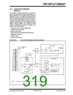
FIGURE 25-1:
CAPACITIVE SENSING BLOCK DIAGRAM
Timer0 Module
CPSCH<3:0>
CPSON(1)
Set
TMR0CS
TMR0IF
T0XCS
T0CKI
CPS0
CPS1
CPS2
CPS3
CPS4
CPS5
CPS6
CPS7
CPS8
CPS9
CPS10
CPS11
CPS12
CPS13
CPS14
CPS15
CPS16
FOSC/4
0
1
Overflow
TMR0
0
1
CPSRNG<1:0>
CPSON
Capacitive
Sensing
Oscillator
Timer1 Module
T1CS<1:0>
CPSOSC
FOSC
FOSC/4
CPSCLK
CPSOUT
Int.
Ref.
0
1
TMR1H:TMR1L
T1OSC/
T1CKI
Ref-
EN
DAC
T1GSEL<1:0>
T1G
0
Ref+
1
FVR
Timer1 Gate
Control Logic
SYNCC1OUT
SYNCC2OUT
CPSRM
Note 1: If CPSON = 0, disabling capacitive sensing, no channel is selected.
2010 Microchip Technology Inc.
Preliminary
DS41414A-page 317

 MICROCHIP [ MICROCHIP ]