PIC16F/LF1946/47
When the TXxREG becomes empty, as indicated by
the TXxIF, the next data byte can be written to TXxREG.
24.3.4
BREAK CHARACTER SEQUENCE
The EUSART module has the capability of sending the
special Break character sequences that are required by
the LIN bus standard. A Break character consists of a
Start bit, followed by 12 ‘0’ bits and a Stop bit.
24.3.5
RECEIVING A BREAK CHARACTER
The Enhanced EUSART module can receive a Break
character in two ways.
To send a Break character, set the SENDB and TXEN
bits of the TXxSTA register. The Break character trans-
mission is then initiated by a write to the TXxREG. The
value of data written to TXxREG will be ignored and all
‘0’s will be transmitted.
The first method to detect a Break character uses the
FERR bit of the RCxSTA register and the Received
data as indicated by RCxREG. The Baud Rate
Generator is assumed to have been initialized to the
expected baud rate.
The SENDB bit is automatically reset by hardware after
the corresponding Stop bit is sent. This allows the user
to preload the transmit FIFO with the next transmit byte
following the Break character (typically, the Sync
character in the LIN specification).
A Break character has been received when;
• RCxIF bit is set
• FERR bit is set
• RCxREG = 00h
The TRMT bit of the TXxSTA register indicates when the
transmit operation is active or Idle, just as it does during
normal transmission. See Figure 24-9 for the timing of
the Break character sequence.
The second method uses the Auto-Wake-up feature
described in Section 24.3.3 “Auto-Wake-up on
Break”. By enabling this feature, the EUSART will
sample the next two transitions on RXx/DTx, cause an
RCxIF interrupt, and receive the next data byte
followed by another interrupt.
24.3.4.1
Break and Sync Transmit Sequence
The following sequence will start a message frame
header made up of a Break, followed by an auto-baud
Sync byte. This sequence is typical of a LIN bus
master.
Note that following a Break character, the user will
typically want to enable the Auto-Baud Detect feature.
For both methods, the user can set the ABDEN bit of
the BAUDxCON register before placing the EUSART in
Sleep mode.
1. Configure the EUSART for the desired mode.
2. Set the TXEN and SENDB bits to enable the
Break sequence.
3. Load the TXxREG with a dummy character to
initiate transmission (the value is ignored).
4. Write ‘55h’ to TXxREG to load the Sync charac-
ter into the transmit FIFO buffer.
5. After the Break has been sent, the SENDB bit is
reset by hardware and the Sync character is
then transmitted.
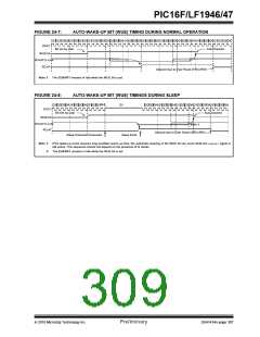
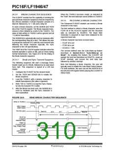
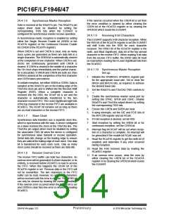
FIGURE 24-9:
SEND BREAK CHARACTER SEQUENCE
Write to TXxREG
Dummy Write
BRG Output
(Shift Clock)
TXx/CKx (pin)
Start bit
bit 0
bit 1
Break
bit 11
Stop bit
TXxIF bit
(Transmit
interrupt Flag)
TRMT bit
(Transmit Shift
Reg. Empty Flag)
SENDB Sampled Here
Auto Cleared
SENDB
(send Break
control bit)
DS41414A-page 308
Preliminary
2010 Microchip Technology Inc.

 MICROCHIP [ MICROCHIP ]