PIC16F/LF1946/47
The first (preferred) method uses the OSCTUNE
register to adjust the HFINTOSC output. Adjusting the
value in the OSCTUNE register allows for fine resolution
changes to the system clock source. See Section 5.2
“Clock Source Types” for more information.
24.2 Clock Accuracy with
Asynchronous Operation
The factory calibrates the internal oscillator block
output (HFINTOSC). However, the HFINTOSC
frequency may drift as VDD or temperature changes,
and this directly affects the asynchronous baud rate.
Two methods may be used to adjust the baud rate
clock, but both require a reference clock source of
some kind.
The other method adjusts the value in the Baud Rate
Generator. This can be done automatically with the
Auto-Baud Detect feature (see Section 24.3.1
“Auto-Baud Detect”). There may not be fine enough
resolution when adjusting the Baud Rate Generator to
compensate for a gradual change in the peripheral
clock frequency.
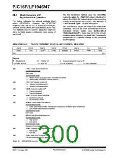
REGISTER 24-1: TXxSTA: TRANSMIT STATUS AND CONTROL REGISTER
R/W-0
CSRC
R/W-0
TX9
R/W-0
R/W-0
SYNC
R/W-0
R/W-0
BRGH
R-1
R/W-0
TX9D
(1)
TXEN
SENDB
TRMT
bit 7
bit 0
Legend:
R = Readable bit
-n = Value at POR
W = Writable bit
‘1’ = Bit is set
U = Unimplemented bit, read as ‘0’
‘0’ = Bit is cleared x = Bit is unknown
bit 7
CSRC: Clock Source Select bit
Asynchronous mode:
Don’t care
Synchronous mode:
1= Master mode (clock generated internally from BRG)
0= Slave mode (clock from external source)
bit 6
bit 5
bit 4
bit 3
TX9: 9-bit Transmit Enable bit
1= Selects 9-bit transmission
0= Selects 8-bit transmission
(1)
TXEN: Transmit Enable bit
1= Transmit enabled
0= Transmit disabled
SYNC: EUSART Mode Select bit
1= Synchronous mode
0= Asynchronous mode
SENDB: Send Break Character bit
Asynchronous mode:
1= Send Sync Break on next transmission (cleared by hardware upon completion)
0= Sync Break transmission completed
Synchronous mode:
Don’t care
bit 2
BRGH: High Baud Rate Select bit
Asynchronous mode:
1= High speed
0= Low speed
Synchronous mode:
Unused in this mode
bit 1
bit 0
TRMT: Transmit Shift Register Status bit
1= TSR empty
0= TSR full
TX9D: Ninth bit of Transmit Data
Can be address/data bit or a parity bit.
Note 1: SREN/CREN overrides TXEN in Sync mode.
DS41414A-page 298
Preliminary
2010 Microchip Technology Inc.

 MICROCHIP [ MICROCHIP ]