PIC16F/LF1946/47
To select an Enhanced PWM Output mode, the PxM bits
of the CCPxCON register must be configured
appropriately.
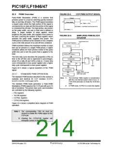
22.4 PWM (Enhanced Mode)
The enhanced PWM function described in this section is
available for CCP modules ECCP1, ECCP2 and
ECCP3, with any differences between modules noted.
The PWM outputs are multiplexed with I/O pins and are
designated PxA, PxB, PxC and PxD. The polarity of the
PWM pins is configurable and is selected by setting the
CCPxM bits in the CCPxCON register appropriately.
The enhanced PWM mode generates a Pulse-Width
Modulation (PWM) signal on up to four different output
pins with up to 10 bits of resolution. The period, duty
cycle, and resolution are controlled by the following
registers:
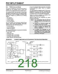
Figure 22-5 shows an example of a simplified block
diagram of the Enhanced PWM module.
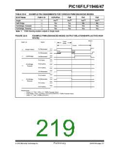
Table 22-8 shows the pin assignments for various
Enhanced PWM modes.
• PRx registers
• TxCON registers
• CCPRxL registers
• CCPxCON registers
Note 1: The corresponding TRIS bit must be
cleared to enable the PWM output on the
CCPx pin.
The ECCP modules have the following additional PWM
registers which control Auto-shutdown, Auto-restart,
Dead-band Delay and PWM Steering modes:
2: Clearing the CCPxCON register will
relinquish control of the CCPx pin.
3: Any pin not used in the enhanced PWM
mode is available for alternate pin
functions, if applicable.
• CCPxAS registers
• PSTRxCON registers
• PWMxCON registers
4: To prevent the generation of an
incomplete waveform when the PWM is
first enabled, the ECCP module waits
until the start of a new PWM period before
generating a PWM signal.
The enhanced PWM module can generate the following
five PWM Output modes:
• Single PWM
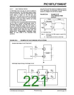
• Half-Bridge PWM
• Full-Bridge PWM, Forward Mode
• Full-Bridge PWM, Reverse Mode
• Single PWM with PWM Steering Mode
FIGURE 22-5:
EXAMPLE SIMPLIFIED BLOCK DIAGRAM OF THE ENHANCED PWM MODE
DCxB<1:0>
PxM<1:0>
CCPxM<3:0>
4
Duty Cycle Registers
2
CCPRxL
CCPx/PxA
CCPx/PxA
PxB
TRISx
TRISx
TRISx
TRISx
CCPRxH (Slave)
Comparator
PxB
Output
Controller
R
S
Q
PxC
PxC
(1)
TMRx
PxD
PxD
Comparator
PRx
Clear Timer,
toggle PWM pin and
latch duty cycle
PWMxCON
Note 1: The 8-bit timer TMRx register is concatenated with the 2-bit internal Q clock, or 2 bits of the prescaler to create the 10-bit time
base.
DS41414A-page 216
Preliminary
2010 Microchip Technology Inc.

 MICROCHIP [ MICROCHIP ]