PIC16F/LF1946/47
TABLE 22-8: EXAMPLE PIN ASSIGNMENTS FOR VARIOUS PWM ENHANCED MODES
ECCP Mode
PxM<1:0>
CCPx/PxA
PxB
PxC
PxD
Single
00
10
01
11
Yes(1)
Yes
Yes(1)
Yes
Yes(1)
No
Yes(1)
No
Half-Bridge
Full-Bridge, Forward
Full-Bridge, Reverse
Yes
Yes
Yes
Yes
Yes
Yes
Yes
Yes
Note 1: PWM Steering enables outputs in Single mode.
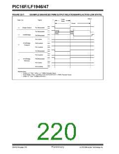
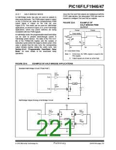
FIGURE 22-6:
EXAMPLE PWM (ENHANCED MODE) OUTPUT RELATIONSHIPS (ACTIVE-HIGH
STATE)
PRX+1
Pulse
Width
0
Signal
PxM<1:0>
Period
PxA Modulated
(Single Output)
00
10
Delay
Delay
PxA Modulated
PxB Modulated
PxA Active
(Half-Bridge)
PxB Inactive
(Full-Bridge,
Forward)
01
PxC Inactive
PxD Modulated
PxA Inactive
PxB Modulated
PxC Active
(Full-Bridge,
Reverse)
11
PxD Inactive
Relationships:
•
•
•
Period = 4 * TOSC * (PRx + 1) * (TMRx Prescale Value)
Pulse Width = TOSC * (CCPRxL<7:0>:CCPxCON<5:4>) * (TMRx Prescale Value)
Delay = 4 * TOSC * (PWMxCON<6:0>)
2010 Microchip Technology Inc.
Preliminary
DS41414A-page 217

 MICROCHIP [ MICROCHIP ]