PIC16F/LF1946/47
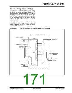
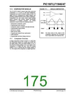
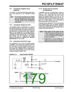
FIGURE 17-1:
SINGLE COMPARATOR
17.0 COMPARATOR MODULE
The PIC16F/LF1946/47 devices have three rail-to-rail
comparators, C1, C2 and C3, with input multiplexing.
Comparators are used to interface analog circuits to a
digital circuit by comparing two analog voltages and
providing a digital indication of their relative magnitudes.
Comparators are very useful mixed signal building
blocks because they provide analog functionality
independent of program execution. The analog
comparator module includes the following features:
VIN+
VIN-
+
Output
–
VIN-
VIN+
• Independent comparator control
• Programmable input selection
• Comparator output is available internally/externally
• Programmable output polarity
• Interrupt-on-change
Output
• Wake-up from Sleep
Note:
The black areas of the output of the
comparator represents the uncertainty
due to input offsets and response time.
• Programmable Speed/Power optimization
• PWM shutdown
• Programmable and fixed voltage reference
17.1
Comparator Overview
A single comparator is shown in Figure 17-1 along with
the relationship between the analog input levels and
the digital output. When the analog voltage at VIN+ is
less than the analog voltage at VIN-, the output of the
comparator is a digital low level. When the analog
voltage at VIN+ is greater than the analog voltage at
VIN-, the output of the comparator is a digital high level.
2010 Microchip Technology Inc.
Preliminary
DS41414A-page 173

 MICROCHIP [ MICROCHIP ]