PIC12F609/615/12HV609/615
The default value of the OSCTUNE register is ‘0’. The
value is a 5-bit two’s complement number.
3.4.1.1
OSCTUNE Register
The oscillator is factory calibrated but can be adjusted
in software by writing to the OSCTUNE register
(Register 3-1).
When the OSCTUNE register is modified, the frequency
will begin shifting to the new frequency. Code execution
continues during this shift. There is no indication that the
shift has occurred.
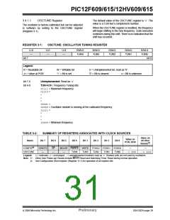
REGISTER 3-1:
OSCTUNE: OSCILLATOR TUNING REGISTER
U-0
—
U-0
—
U-0
—
R/W-0
TUN4
R/W-0
TUN3
R/W-0
TUN2
R/W-0
TUN1
R/W-0
TUN0
bit 7
bit 0
Legend:
R = Readable bit
-n = Value at POR
W = Writable bit
‘1’ = Bit is set
U = Unimplemented bit, read as ‘0’
‘0’ = Bit is cleared x = Bit is unknown
bit 7-5
bit 4-0
Unimplemented: Read as ‘0’
TUN<4:0>: Frequency Tuning bits
01111= Maximum frequency
01110=
•
•
•
00001=
00000= Oscillator module is running at the calibrated frequency.
11111=
•
•
•
10000= Minimum frequency
TABLE 3-2:
SUMMARY OF REGISTERS ASSOCIATED WITH CLOCK SOURCES
Value on
all other
Resets
Value on
POR, BOR
Name
Bit 7
Bit 6
Bit 5
Bit 4
Bit 3
Bit 2
Bit 1
Bit 0
(1)
(2)
CONFIG
IOSCFS
—
CP
—
MCLRE PWRTE
TUN4
WDTE
TUN3
FOSC2
TUN2
FOSC1
TUN1
FOSC0
TUN0
—
—
OSCTUNE
—
---0 0000 ---u uuuu
Legend:
x= unknown, u= unchanged, –= unimplemented locations read as ‘0’. Shaded cells are not used by oscillators.
Note 1: Other (non Power-up) Resets include MCLR Reset and Watchdog Timer Reset during normal operation.
2: See Configuration Word register (Register 11-1) for operation of all register bits.
© 2006 Microchip Technology Inc.
Preliminary
DS41302A-page 29

 MICROCHIP [ MICROCHIP ]