PIC12F609/615/12HV609/615
The Oscillator module can be configured in one of eight
clock modes.
3.0
3.1
OSCILLATOR MODULE
Overview
1. EC – External clock with I/O on OSC2/CLKOUT.
2. LP – 32 kHz Low-Power Crystal mode.
The Oscillator module has a wide variety of clock
sources and selection features that allow it to be used
in a wide range of applications while maximizing perfor-
mance and minimizing power consumption. Figure 3-1
illustrates a block diagram of the Oscillator module.
3. XT – Medium Gain Crystal or Ceramic Resonator
Oscillator mode.
4. HS – High Gain Crystal or Ceramic Resonator
mode.
5. RC – External Resistor-Capacitor (RC) with
FOSC/4 output on OSC2/CLKOUT.
Clock sources can be configured from external
oscillators, quartz crystal resonators, ceramic resonators
and Resistor-Capacitor (RC) circuits. In addition, the
system clock source can be configured with a choice of
two selectable speeds: internal or external system clock
source.
6. RCIO – External Resistor-Capacitor (RC) with
I/O on OSC2/CLKOUT.
7. INTOSC – Internal oscillator with FOSC/4 output
on OSC2 and I/O on OSC1/CLKIN.
8. INTOSCIO – Internal oscillator with I/O on
OSC1/CLKIN and OSC2/CLKOUT.
Clock Source modes are configured by the FOSC<2:0>
bits in the Configuration Word register (CONFIG). The
Internal Oscillator module provides a selectable system
clock mode of either 4 MHz (Postscaler) or 8 MHz
(INTOSC).
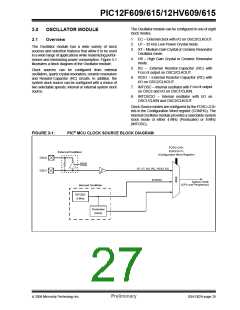
FIGURE 3-1:
PIC® MCU CLOCK SOURCE BLOCK DIAGRAM
FOSC<2:0>
IOSCFS<7>
(Configuration Word Register)
External Oscillator
OSC2
OSC1
Sleep
LP, XT, HS, RC, RCIO, EC
INTOSC
System Clock
(CPU and Peripherals)
Internal Oscillator
INTOSC
8 MHz
Postscaler
4 MHz
© 2006 Microchip Technology Inc.
Preliminary
DS41302A-page 25

 MICROCHIP [ MICROCHIP ]