PIC12(L)F1501
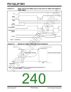
FIGURE 27-7:
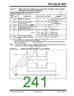
RESET, WATCHDOG TIMER, OSCILLATOR START-UP TIMER AND POWER-UP
TIMER TIMING
VDD
MCLR
30
Internal
POR
33
PWRT
Time-out
Internal Reset(1)
Watchdog Timer
Reset(1)
31
34
34
I/O pins
Note 1: Asserted low.
FIGURE 27-8:
BROWN-OUT RESET TIMING AND CHARACTERISTICS
VDD
VBOR and VHYST
VBOR
(Device in Brown-out Reset)
(Device not in Brown-out Reset)
37
Reset
33(1)
(due to BOR)
Note 1: 64 ms delay only if PWRTE bit in the Configuration Words is programmed to ‘0’.
2 ms delay if PWRTE = 0and VREGEN = 1.
DS41615A-page 240
Preliminary
2011 Microchip Technology Inc.

 MICROCHIP [ MICROCHIP ]