PIC12(L)F1501
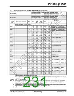
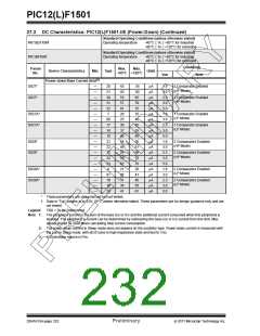
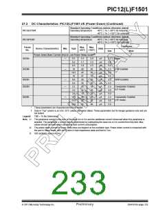
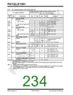
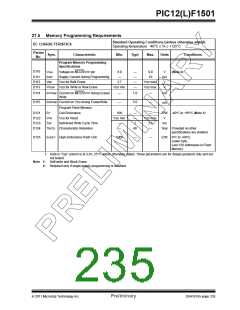
27.3 DC Characteristics: PIC12(L)F1501-I/E (Power-Down) (Continued)
Standard Operating Conditions (unless otherwise stated)
PIC12LF1501
Operating temperature
-40°C TA +85°C for industrial
-40°C TA +125°C for extended
Standard Operating Conditions (unless otherwise stated)
PIC12F1501
Operating temperature
-40°C TA +85°C for industrial
-40°C TA +125°C for extended
Conditions
Note
Param
No.
Max.
+85°C +125°C
Max.
Device Characteristics
Min.
Typ†
Units
VDD
(2)
Power-down Base Current (IPD) in Low-Power Sleep mode
D029A
D029B
—
—
0.1
0.2
1.5
1.7
1.9
40
45
47
20
24
13
14
15
40
42
43
2.0
2.3
2.5
45
50
52
25
30
18
19
20
45
47
48
A
A
A
A
A
A
A
A
A
A
A
A
A
A
2.3
3.0
5.0
2.3
3.0
5.0
3.0
5.0
2.3
3.0
5.0
2.3
3.0
5.0
Base
0.3
18
FVR Enabled
BOR Enabled
18.5
19
D029C
D029D
—
—
8.0
9.5
3.2
Comparator Enabled
(LP mode)
3.5
3.6
D029E
—
17.0
17.5
18.0
Comparator Enabled
(HP mode)
*
These parameters are characterized but not tested.
†
Data in “Typ” column is at 3.0V, 25°C unless otherwise stated. These parameters are for design guidance only and are
not tested.
Legend:
TBD = To Be Determined
Note 1: The peripheral current is the sum of the base IDD or IPD and the additional current consumed when this peripheral is
enabled. The peripheral current can be determined by subtracting the base IDD or IPD current from this limit. Max
values should be used when calculating total current consumption.
2: The power-down current in Sleep mode does not depend on the oscillator type. Power-down current is measured with
the part in Sleep mode, with all I/O pins in high-impedance state and tied to VDD.
3: A/D oscillator source is FRC.
2011 Microchip Technology Inc.
Preliminary
DS41615A-page 233

 MICROCHIP [ MICROCHIP ]