MCP6271/1R/2/3/4/5
4.9.3.5
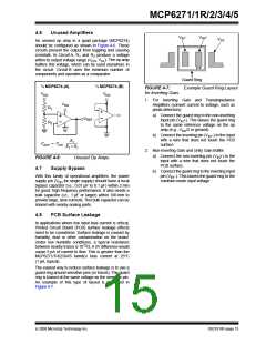
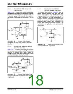
Second Order MFB with an Extra
Pole-Zero Pair
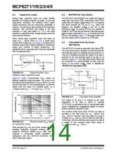
4.9.3.7
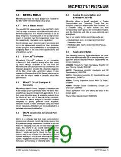
Capacitorless Second Order
Low-Pass filter with Chip Select
Figure 4-14 is a second order multiple feedback low-
pass filter with Chip Select. Use the FilterLab® software
from Microchip Technology Inc. to determine the R and
C values for op amp A’s second order filter. Op amp B
can be used to add a pole-zero pair using C3, R6 and
R7.
The low-pass filter shown in Figure 4-16 does not
require external capacitors and uses only three
external resistors; the op amp’s GBWP sets the corner
frequency. R1 and R2 are used to set the circuit gain. R3
is used to set the Q. To avoid gain peaking in the
frequency response, Q needs to be low (lower values
need to be selected for R3). Note that the amplifier
bandwidth varies greatly over temperature and
process. This configuration, however, provides a low
cost solution for applications with high bandwidth
requirements.
C3
R7
R6
R1
C1
R1
R2
R3
R2
R5
VOUT
B
VIN
VIN
R3
A
A
VDD
MCP6275
VOUT
B
VREF
R4
MCP6275
CS
FIGURE 4-14:
Feedback Low-Pass Filter with an Extra Pole-
Zero Pair.
Second Order Multiple
CS
FIGURE 4-16:
Capacitorless Second Order
Low-Pass Filter with Chip Select.
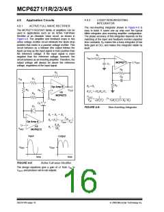
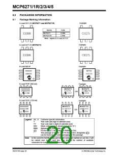
4.9.3.6
Second Order Sallen-Key with an
Extra Pole-Zero Pair
Figure 4-15 is a second order Sallen-Key low-pass
filter with Chip Select. Use the Filterlab® software from
Microchip to determine the R and C values for
op amp A’s second order filter. Op amp B can be used
to add a pole-zero pair using C3, R5 and R6.
C3
R6
R5
R1
R2
VOUT
B
R4
R3
C2
A
VIN
MCP6275
C1
CS
FIGURE 4-15:
Second Order Sallen-Key
Low-Pass Filter with an Extra Pole-Zero Pair and
Chip Select.
DS21810F-page 18
© 2008 Microchip Technology Inc.

 MICROCHIP [ MICROCHIP ]