MCP3905/06
The output of the low-pass filter is accumulated in the
DTF converter. This accumulation is compared to a
4.6
Low-Pass Filter and DTF
Converter
different digital threshold for FOUT0/1 and HFOUT
,
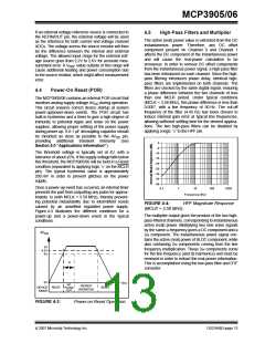
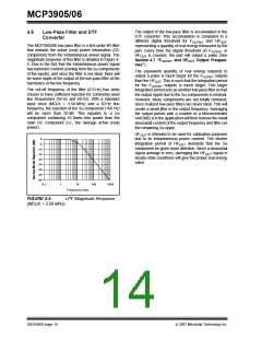
The MCP3905/06 low-pass filter is a first-order IIR filter
that extracts the active (real) power information (DC
component) from the instantaneous power signal. The
magnitude response of this filter is detailed in Figure 4-
5. Due to the fact that the instantaneous power signal
has harmonic content (coming from the 2ω components
of the inputs), and since the filter is not ideal, there will
be some ripple at the output of the low-pass filter at the
harmonics of the line frequency.
representing a quantity of real energy measured by the
part. Every time the digital threshold on FOUT0/1 or
HFOUT is crossed, the part will output a pulse (See
Section 4.7 “FOUT0/1 and HFOUT Output Frequen-
cies”).
The equivalent quantity of real energy required to
output a pulse is much larger for the FOUT0/1 outputs
than the HFOUT. This is such that the integration period
for the FOUT0/1 outputs is much larger. This larger
integration period acts as another low-pass filter so that
the output ripple due to the 2ω components is minimal.
However, these components are not totally removed,
since realized low-pass filters are never ideal. This will
create a small jitter in the output frequency. Averaging
the output pulses with a counter or a Microcontroller
Unit (MCU) in the application will then remove the small
sinusoidal content of the output frequency and filter out
the remaining 2ω ripple.
The cut-off frequency of the filter (8.9 Hz) has been
chosen to have sufficient rejection for commonly-used
line frequencies (50 Hz and 60 Hz). With a standard
input clock (MCLK = 3.58 MHz) and a 50 Hz line
frequency, the rejection of the 2ω component (100 Hz)
will be more than 20 dB. This equates to a 2ω
component containing 10 times less power than the
main DC component (i.e., the average active (real)
power).
HFOUT is intended to be used for calibration purposes
due to its instantaneous power content. The shorter
integration period of HFOUT demands that the 2ω
component be given more attention. Since a sinusoidal
signal average is zero, averaging the HFOUT signal in
steady-state conditions will give the proper real energy
value.
0
-5
-10
-15
-20
-25
-30
-35
-40
0.1
1
10
100
1000
Frequency (Hz)
FIGURE 4-5:
LPF Magnitude Response
(MCLK = 3.58 MHz).
DS21948D-page 14
© 2007 Microchip Technology Inc.

 MICROCHIP [ MICROCHIP ]