MCP3905/06
The high-frequency output HFOUT has lower
integration times and, thus, higher frequencies. The
output frequency value can be calculated with the
following equation:
MINIMAL OUTPUT FREQUENCY FOR
NO-LOAD THRESHOLD
The MCP3905/06 also includes, on each output
frequency, a no-load threshold circuit that will eliminate
any creep effects in the meter. The outputs will not
show any pulse if the output frequency falls below the
no-load threshold. The minimum output frequency on
FOUT0/1 and HFOUT is equal to 0.0015% of the
maximum output frequency (respectively FC and HFC)
for each of the F2, F1 and F0 selections (see Table 4-3
and Table 4-4); except when F2, F1, F0 = 011. In this
last configuration, the no-load threshold feature is
disabled. The selection of FC will determine the start-up
current load. In order to respect the IEC standards
requirements, the meter will have to be designed to
allow start-up currents compatible with the standards
by choosing the FC value matching these
requirements. For additional applications information
on no-load threshold, startup current and other meter
design points, refer to AN994, "IEC Compliant Active
Energy Meter Design Using The MCP3905/6”,
(DS00994).
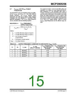
EQUATION 4-2:
HFOUT FREQUENCY
OUTPUT EQUATION
8.06 × V0 × V1 × G × HFC
---------------------------------------------------------------
HFOUT(Hz) =
2
(VREF
)
Where:
V0 = the RMS differential voltage on Channel 0
V1 = the RMS differential voltage on Channel 1
G = the PGA gain on Channel 0
(current channel)
FC = the frequency constant selected
VREF = the voltage reference
The constant HFC depends on the FOUT0 and FOUT1
digital settings with the Table 4-4.
The detailed timings of the output pulses are described
in the Timing Characteristics table (see Section 1.0
“Electrical Characteristics” and Figure 1-1).
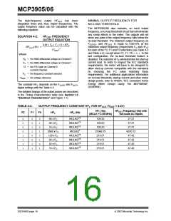
TABLE 4-4:
OUTPUT FREQUENCY CONSTANT HFC FOR HFOUT (VREF = 2.4V)
HFC (Hz)
(MCLK = 3.58 MHz)
HFOUT Frequency (Hz) with
full-scale AC Inputs
F2
F1
F0
HFC
HFC (Hz)
0
0
0
0
1
1
1
1
0
0
1
1
0
0
1
1
0
1
0
1
0
1
0
1
64 x FC
32 x FC
16 x FC
2048 x FC
128 x FC
64 x FC
32 x FC
16 x FC
MCLK/215
MCLK/215
MCLK/215
MCLK/27
MCLK/216
MCLK/216
MCLK/216
MCLK/216
109.25
109.25
109.25
27968.75
219.51
219.51
219.51
219.51
27.21
27.21
27.21
6070.12
47.42
47.42
47.42
47.42
DS21948D-page 16
© 2007 Microchip Technology Inc.

 MICROCHIP [ MICROCHIP ]