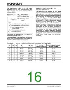
MCP3905/06
For a given DC input V, the DC and RMS values are
equivalent. For a given AC input signal with peak-to-
peak amplitude of V, the equivalent RMS value is
V/sqrt(2), assuming purely sinusoidal signals. Note that
since the active (real) power is the product of two RMS
inputs, the output frequencies of an AC signal is half
that of the DC equivalent signal, again assuming purely
sinusoidal AC signals. The constant FC depends on the
FOUT0 and FOUT1 digital settings. Table 4-3 shows
FOUT0/1 output frequencies for the different logic set-
tings.
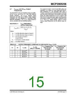
4.7
F
and HF
Output
OUT
OUT0/1
Frequencies
The thresholds for the accumulated energy are differ-
ent for FOUT0/1 and HFOUT (i.e., they have different
transfer functions). The FOUT0/1 allowed output
frequencies are quite low in order to allow superior
integration time (see Section 4.6 “Low-Pass Filter
and DTF Converter”). The FOUT0/1 output frequency
can be calculated with the following equation:
EQUATION 4-1:
FOUT FREQUENCY
OUTPUT EQUATION
8.06 × V0 × V1 × G × FC
----------------------------------------------------------
FOUT(Hz) =
2
(VREF
)
Where:
V0
V1
=
=
the RMS differential voltage on Channel 0
the RMS differential voltage on Channel 1
G = the PGA gain on Channel 0
(current channel)
FC
=
=
the frequency constant selected
the voltage reference
VREF
TABLE 4-3:
F1
OUTPUT FREQUENCY CONSTANT FC FOR FOUT0/1 (VREF = 2.4V)
F
OUT Frequency (Hz)
with Full-Scale
DC Inputs
FOUT Frequency (Hz)
FC (Hz)
(MCLK = 3.58 MHz)
F0
FC (Hz)
with Full-Scale
AC Inputs
0
0
1
1
0
1
0
1
MCLK/221
MCLK/220
MCLK/219
MCLK/218
1.71
3.41
0.74
1.48
2.96
5.93
0.37
0.74
1.48
2.96
6.83
13.66
© 2007 Microchip Technology Inc.
DS21948D-page 15

 MICROCHIP [ MICROCHIP ]