MCP2515
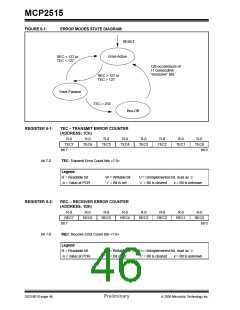
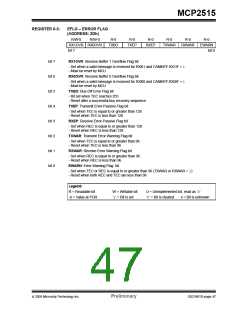
FIGURE 6-1:
ERROR MODES STATE DIAGRAM
RESET
Error-Active
REC < 127 or
TEC < 127
128 occurrences of
11 consecutive
“recessive” bits
REC > 127 or
TEC > 127
Error-Passive
TEC > 255
Bus-Off
REGISTER 6-1:
TEC – TRANSMIT ERROR COUNTER
(ADDRESS: 1Ch)
R-0
R-0
R-0
R-0
R-0
R-0
R-0
TEC1
R-0
TEC7
TEC6
TEC5
TEC4
TEC3
TEC2
TEC0
bit 7
bit 0
bit 7-0
TEC: Transmit Error Count bits <7:0>
Legend:
R = Readable bit
-n = Value at POR
W = Writable bit
U = Unimplemented bit, read as ‘0’
‘0’ = Bit is cleared x = Bit is unknown
‘1’ = Bit is set
REGISTER 6-2:
REC – RECEIVER ERROR COUNTER
(ADDRESS: 1Dh)
R-0
R-0
R-0
R-0
R-0
R-0
R-0
R-0
REC7
REC6
REC5
REC4
REC3
REC2
REC1
REC0
bit 7
bit 0
bit 7-0
REC: Receive Error Count bits <7:0>
Legend:
R = Readable bit
-n = Value at POR
W = Writable bit
U = Unimplemented bit, read as ‘0’
‘0’ = Bit is cleared x = Bit is unknown
‘1’ = Bit is set
DS21801D-page 46
Preliminary
© 2005 Microchip Technology Inc.

 MICROCHIP [ MICROCHIP ]