MCP2515
7.2
Transmit Interrupt
7.0
INTERRUPTS
When
the
transmit
interrupt
is
enabled
The MCP2515 has eight sources of interrupts. The
CANINTE register contains the individual interrupt
enable bits for each interrupt source. The CANINTF
register contains the corresponding interrupt flag bit for
each interrupt source. When an interrupt occurs, the
INT pin is driven low by the MCP2515 and will remain
low until the interrupt is cleared by the MCU. An
interrupt can not be cleared if the respective condition
still prevails.
(CANINTE.TXnIE = 1), an interrupt will be generated on
the INT pin once the associated transmit buffer
becomes empty and is ready to be loaded with a new
message. The CANINTF.TXnIF bit will be set to indicate
the source of the interrupt. The interrupt is cleared by
clearing the TXnIF bit.
7.3
Receive Interrupt
It is recommended that the bit modify command be
used to reset flag bits in the CANINTF register rather
than normal write operations. This is done to prevent
unintentionally changing a flag that changes during the
write command, potentially causing an interrupt to be
missed.
When
the
receive
interrupt
is
enabled
(CANINTE.RXnIE = 1), an interrupt will be generated
on the INT pin once a message has been successfully
received and loaded into the associated receive buffer.
This interrupt is activated immediately after receiving
the EOF field. The CANINTF.RXnIF bit will be set to
indicate the source of the interrupt. The interrupt is
cleared by clearing the RXnIF bit.
It should be noted that the CANINTF flags are
read/write and an interrupt can be generated by the
MCU setting any of these bits, provided the associated
CANINTE bit is also set.
7.4
Message Error Interrupt
When an error occurs during the transmission or
reception of a message, the message error flag
(CANINTF.MERRF) will be set and, if the
CANINTE.MERRE bit is set, an interrupt will be gener-
ated on the INT pin. This is intended to be used to
facilitate baud rate determination when used in
conjunction with Listen-only mode.
7.1
Interrupt Code Bits
The source of a pending interrupt is indicated in the
CANSTAT.ICOD (interrupt code) bits, as indicated in
Register 10-2. In the event that multiple interrupts
occur, the INT will remain low until all interrupts have
been reset by the MCU. The CANSTAT.ICOD bits will
reflect the code for the highest priority interrupt that is
currently pending. Interrupts are internally prioritized
such that the lower the ICOD value, the higher the
interrupt priority. Once the highest priority interrupt
condition has been cleared, the code for the next
highest priority interrupt that is pending (if any) will be
reflected by the ICOD bits (see Table 7-1). Only those
interrupt sources that have their associated CANINTE
enable bit set will be reflected in the ICOD bits.
7.5
Bus Activity Wakeup Interrupt
When the MCP2515 is in Sleep mode and the bus activ-
ity wakeup interrupt is enabled (CANINTE.WAKIE = 1),
an interrupt will be generated on the INT pin and the
CANINTF.WAKIF bit will be set when activity is
detected on the CAN bus. This interrupt causes the
MCP2515 to exit Sleep mode. The interrupt is reset by
clearing the WAKIF bit.
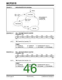
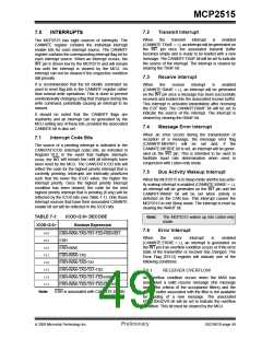
TABLE 7-1:
ICOD<2:0>
ICOD<2:0> DECODE
Boolean Expression
Note:
The MCP2515 wakes up into Listen-only
mode.
7.6
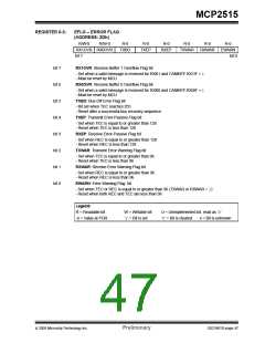
Error Interrupt
000
001
010
011
100
101
110
111
ERR•WAK•TX0•TX1•TX2•RX0•RX1
ERR
When
the
error
interrupt
is
enabled
(CANINTE.ERRIE = 1), an interrupt is generated on
the INT pin if an overflow condition occurs or if the error
state of the transmitter or receiver has changed. The
Error Flag (EFLG) register will indicate one of the
following conditions.
ERR•WAK
ERR•WAK•TX0
ERR•WAK•TX0•TX1
ERR•WAK•TX0•TX1•TX2
ERR•WAK•TX0•TX1•TX2•RX0
ERR•WAK•TX0•TX1•TX2•RX0•RX1
7.6.1
RECEIVER OVERFLOW
An overflow condition occurs when the MAB has
assembled a valid receive message (the message
meets the criteria of the acceptance filters) and the
receive buffer associated with the filter is not available
for loading of a new message. The associated
EFLG.RXnOVR bit will be set to indicate the overflow
condition. This bit must be cleared by the MCU.
Note:
ERR is associated with CANINTE,ERRIE.
© 2005 Microchip Technology Inc.
Preliminary
DS21801D-page 49

 MICROCHIP [ MICROCHIP ]