MCP2515
6.6
Error States
6.0
ERROR DETECTION
Detected errors are made known to all other nodes via
error frames. The transmission of the erroneous mes-
sage is aborted and the frame is repeated as soon as
possible. Furthermore, each CAN node is in one of the
three error states according to the value of the internal
error counters:
The CAN protocol provides sophisticated error
detection mechanisms. The following errors can be
detected.
6.1
CRC Error
With the Cyclic Redundancy Check (CRC), the
transmitter calculates special check bits for the bit
sequence from the start of a frame until the end of the
data field. This CRC sequence is transmitted in the
CRC Field. The receiving node also calculates the
CRC sequence using the same formula and performs
a comparison to the received sequence. If a mismatch
is detected, a CRC error has occurred and an error
frame is generated. The message is repeated.
1. Error-active.
2. Error-passive.
3. Bus-off (transmitter only).
The error-active state is the usual state where the node
can transmit messages and active error frames (made
of dominant bits) without any restrictions.
In the error-passive state, messages and passive error
frames (made of recessive bits) may be transmitted.
6.2
Acknowledge Error
The bus-off state makes it temporarily impossible for
the station to participate in the bus communication.
During this state, messages can neither be received or
transmitted. Only transmitters can go bus-off.
In the acknowledge field of a message, the transmitter
checks if the acknowledge slot (which has been sent
out as a recessive bit) contains a dominant bit. If not,
no other node has received the frame correctly. An
acknowledge error has occurred, an error frame is
generated and the message will have to be repeated.
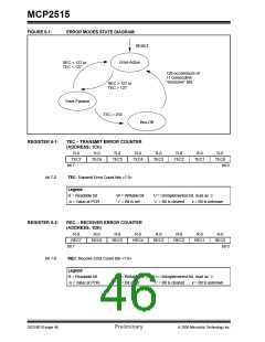
6.7
Error Modes and Error Counters
The MCP2515 contains two error counters: the
Receive Error Counter (REC) (see Register 6-2) and
the Transmit Error Counter (TEC) (see Register 6-1).
The values of both counters can be read by the MCU.
These counters are incremented/decremented in
accordance with the CAN bus specification.
6.3
Form Error
If a node detects a dominant bit in one of the four
segments (including end-of-frame, interframe space,
acknowledge delimiter or CRC delimiter), a form error
has occurred and an error frame is generated. The
message is repeated.
The MCP2515 is error-active if both error counters are
below the error-passive limit of 128.
It is error-passive if at least one of the error counters
equals or exceeds 128.
6.4
Bit Error
A bit error occurs if a transmitter detects the opposite
bit level to what it transmitted (i.e., transmitted a
dominant and detected a recessive, or transmitted a
recessive and detected a dominant).
It goes to bus-off if the TEC exceeds the bus-off limit of
255. The device remains in this state until the bus-off
recovery sequence is received. The bus-off recovery
sequence consists of 128 occurrences and 11 consec-
utive recessive bits (see Figure 6-1).
Exception: In the case where the transmitter sends a
recessive bit and a dominant bit is detected during the
arbitration field and the acknowledge slot, no bit error is
generated because normal arbitration is occurring.
Note:
The MCP2515, after going bus-off, will
recover back to error-active without any
intervention by the MCU if the bus remains
idle for 128 x 11 bit times. If this is not
desired, the error interrupt service routine
should address this.
6.5
Stuff Error
lf, between the start-of-frame and the CRC delimiter,
six consecutive bits with the same polarity are
detected, the bit-stuffing rule has been violated. A stuff
error occurs and an error frame is generated. The
message is repeated.
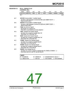
The Current Error mode of the MCP2515 can be read
by the MCU via the EFLG register (see Register 6-3).
Additionally, there is an error state warning flag bit
(EFLG:EWARN) which is set if at least one of the error
counters equals or exceeds the error warning limit of
96. EWARN is reset if both error counters are less than
the error warning limit.
© 2005 Microchip Technology Inc.
Preliminary
DS21801D-page 45

 MICROCHIP [ MICROCHIP ]