MCP2515
5.3
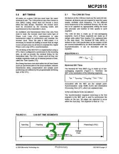
Programming Time Segments
5.5
Bit Timing Configuration
Registers
Some requirements for programming of the time
segments:
The configuration registers (CNF1, CNF2, CNF3)
control the bit timing for the CAN bus interface. These
registers can only be modified when the MCP2515 is in
Configuration mode (see Section 10.0 “Modes of
Operation”).
• PropSeg + PS1 >= PS2
• PropSeg + PS1 >= TDELAY
• PS2 > SJW
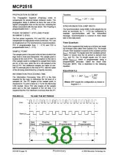
For example, assuming that a 125 kHz CAN baud rate
with FOSC = 20 MHz is desired:
5.5.1
CNF1
TOSC
=
50 ns, choose BRP<5:0> = 04h, then
The BRP<5:0> bits control the baud rate prescaler.
These bits set the length of TQ relative to the OSC1
input frequency, with the minimum TQ length being
TQ = 500 ns. To obtain 125 kHz, the bit time must be
16 TQ.
2 TOSC (when BRP<5:0>
SJW<1:0> bits select the SJW in terms of number of
TQs.
=
‘b000000’). The
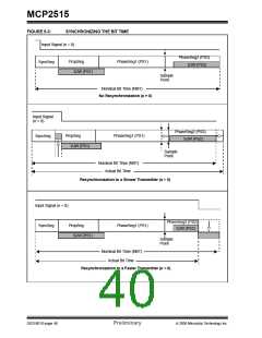
Typically, the sampling of the bit should take place at
about 60-70% of the bit time, depending on the system
parameters. Also, typically, the TDELAY is 1-2 TQ.
SyncSeg = 1 TQ and PropSeg = 2 TQ. So setting
PS1 = 7 TQ would place the sample at 10 TQ after the
transition. This would leave 6 TQ for PS2.
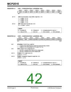
5.5.2
CNF2
The PRSEG<2:0> bits set the length (in TQ’s) of the
propagation segment. The PHSEG1<2:0> bits set the
length (in TQ’s) of PS1.
Since PS2 is 6, according to the rules, SJW could be a
maximum of 4 TQ. However, a large SJW is typically
only necessary when the clock generation of the differ-
ent nodes is inaccurate or unstable, such as using
ceramic resonators. So a SJW of 1 is usually enough.
The SAM bit controls how many times the RXCAN pin
is sampled. Setting this bit to a ‘1’ causes the bus to be
sampled three times: twice at TQ/2 before the sample
point and once at the normal sample point (which is at
the end of PS1). The value of the bus is determined to
be the majority sampled. If the SAM bit is set to a ‘0’,
the RXCAN pin is sampled only once at the sample
point.
5.4
Oscillator Tolerance
The bit timing requirements allow ceramic resonators
to be used in applications with transmission rates of up
to 125 kbit/sec as a rule of thumb. For the full bus
speed range of the CAN protocol, a quartz oscillator is
required. A maximum node-to-node oscillator variation
of 1.7% is allowed.
The BTLMODE bit controls how the length of PS2 is
determined. If this bit is set to a ‘1’, the length of PS2 is
determined by the PHSEG2<2:0> bits of CNF3 (see
Section 5.5.3 “CNF3”). If the BTLMODE bit is set to a
‘0’, the length of PS2 is greater than that of PS1 and the
information processing time (which is fixed at 2 TQ for
the MCP2515).
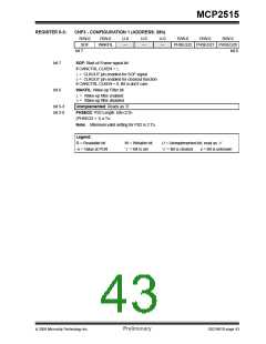
5.5.3
CNF3
The PHSEG2<2:0> bits set the length (in TQ’s) of PS2,
if the CNF2.BTLMODE bit is set to a ‘1’. If the
BTLMODE bit is set to a ‘0’, the PHSEG2<2:0> bits
have no effect.
© 2005 Microchip Technology Inc.
Preliminary
DS21801D-page 41

 MICROCHIP [ MICROCHIP ]