MCP23018/MCP23S18
1.6.7
PULL-UP RESISTOR
CONFIGURATION REGISTER
The GPPU register controls the pull-up resistors for the
port pins. If a bit is set the corresponding port pin is
internally pulled up with an internal resistor.
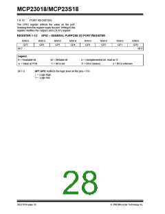
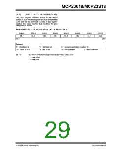
REGISTER 1-9:
GPPU – GPIO PULL-UP RESISTOR REGISTER
R/W-0
PU7
R/W-0
PU6
R/W-0
PU5
R/W-0
PU4
R/W-0
PU3
R/W-0
PU2
R/W-0
PU1
R/W-0
PU0
bit 7
bit 0
Legend:
R = Readable bit
-n = Value at POR
W = Writable bit
‘1’ = Bit is set
U = Unimplemented bit, read as ‘0’
‘0’ = Bit is cleared x = Bit is unknown
bit 7-0
PU7:PU0: Controls the internal pull-up resistors on each pin (when configured as an input or output)
<7:0>.
1= Pull-up enabled.
0= Pull-up disabled.
FIGURE 1-10:
TYPICAL PERFORMANCE CURVE FOR THE INTERNAL PULL-UP RESISTORS
GPIO Pin Internal Pull-up Current vs VDD
400
350
300
250
200
150
100
50
T = -40°C
T = +25°C
T = +125°C
T = +85°C
0
1.5
2
2.5
3
3.5
(V)
4
4.5
5
5.5
V
DD
© 2008 Microchip Technology Inc.
DS22103A-page 25

 MICROCHIP [ MICROCHIP ]