ENC28J60
A common-mode choke on the TPOUT interface,
placed between the TPOUT pins and the Ethernet
transformer (not shown), is not recommend. If a com-
mon-mode choke is used to reduce EMI emissions, it
should be placed between the Ethernet transformer
and pins 1 and 2 of the RJ-45 connector. Many Ether-
net transformer modules include common-mode
chokes inside the same device package. The trans-
formers should have at least the isolation rating speci-
fied in Table 16-5 to protect against static voltages and
meet IEEE 802.3 isolation requirements (see
Section 16.0 “Electrical Characteristics” for specific
transformer requirements). Both transmit and receive
interfaces additionally require two resistors and a
capacitor to properly terminate the transmission line,
minimizing signal reflections.
2.4
Magnetics, Termination and Other
External Components
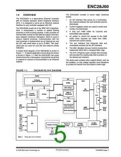
To complete the Ethernet interface, the ENC28J60
requires several standard components to be installed
externally. These components should be connected as
shown in Figure 2-4.
The internal analog circuitry in the PHY module requires
that an external 2.32 kΩ, 1% resistor be attached from
RBIAS to ground. The resistor influences the TPOUT+/-
signal amplitude. The resistor should be placed as close
as possible to the chip with no immediately adjacent
signal traces to prevent noise capacitively coupling into
the pin and affecting the transmit behavior. It is
recommended that the resistor be a surface mount type.
Some of the device’s digital logic operates at a nominal
2.5V. An on-chip voltage regulator is incorporated to
generate this voltage. The only external component
required is an external filter capacitor, connected from
VCAP to ground. The capacitor must have low equiva-
lent-series resistance (ESR), with a typical value of
10 μF, and a minimum value of 1 μF. The internal regu-
lator is not designed to drive external loads.
All power supply pins must be externally connected to
the same power source. Similarly, all ground refer-
ences must be externally connected to the same
ground node. Each VDD and VSS pin pair should have
a 0.1 μF ceramic bypass capacitor (not shown in the
schematic) placed as close to the pins as possible.
Since relatively high currents are necessary to operate
the twisted-pair interface, all wires should be kept as
short as possible. Reasonable wire widths should be
used on power wires to reduce resistive loss. If the
differential data lines cannot be kept short, they should
be routed in such a way as to have a 100Ω character-
istic impedance.
On the TPIN+/TPIN- and TPOUT+/TPOUT- pins,
1:1 center-taped pulse transformers rated for Ethernet
operations are required. When the Ethernet module is
enabled, current is continually sunk through both
TPOUT pins. When the PHY is actively transmitting, a
differential voltage is created on the Ethernet cable by
varying the relative current sunk by TPOUT+ compared
to TPOUT-.
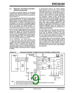
FIGURE 2-4:
ENC28J60 ETHERNET TERMINATION AND EXTERNAL CONNECTIONS
3.3V
RJ-45
ENC28J60
1
MCU
TPOUT+
Ferrite
1
Bead(1,3)
49.9Ω, 1%
I/O
CS
SCK
SI
SCK
2
3
4
5
6
7
8
0.1 μF(3)
SDO
SDI
49.9Ω, 1%
SO
TPOUT-
TPIN+
1:1 CT
1:1 CT
Level
Shift
49.9Ω, 1%
Logic(2)
0.1 μF
49.9Ω, 1%
INT0
INT
TPIN-
RBIAS
LEDB
VCAP
LEDA
75Ω(3) 75Ω(3) 75Ω(3) 75Ω(3)
1 nF, 2 kV(3)
2.32 kΩ, 1%
10 μF
Note 1: Ferrite Bead should be rated for at least 80 mA.
2: Required only if the microcontroller is operating at 5V. See Section 2.5 “I/O Levels” for more information.
3: These components are installed for EMI reduction purposes.
© 2006 Microchip Technology Inc.
Preliminary
DS39662B-page 7

 MICROCHIP [ MICROCHIP ]