4.3
AC Characteristics
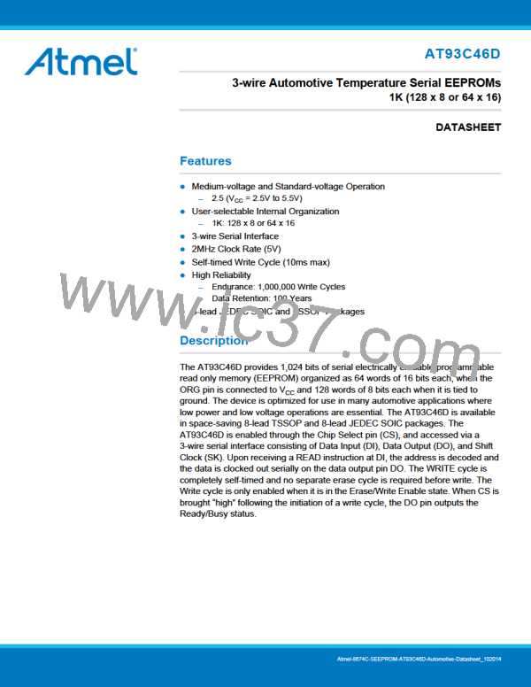
Table 4-3.
AC Characteristics
Applicable over recommended operating range from TA = 40°C to + 125°C, VCC = As Specified, CL = 1 TTL Gate and
100pF (unless otherwise noted).
Symbol
Parameter
Test Condition
Min
0
Typ
Max
2
Units
4.5V VCC 5.5V
2.5V VCC 5.5V
4.5V VCC 5.5V
2.5V VCC 5.5V
4.5V VCC 5.5V
2.5V VCC 5.5V
4.5V VCC 5.5V
2.5V VCC 5.5V
fSK
SK Clock Frequency
MHz
0
1
250
250
250
250
250
250
50
tSKH
tSKL
tCS
SK High Time
ns
ns
ns
ns
SK Low Time
Minimum CS Low Time
CS Setup Time
4.5V VCC 5.5V
2.5V VCC 5.5V
4.5V VCC 5.5V
2.5V VCC 5.5V
tCSS
Relative to SK
50
100
100
0
tDIS
tCSH
tDIH
DI Setup Time
CS Hold Time
DI Hold Time
Relative to SK
Relative to SK
Relative to SK
ns
ns
ns
4.5V VCC 5.5V
2.5V VCC 5.5V
4.5V VCC 5.5V
2.5V VCC 5.5V
4.5V VCC 5.5V
2.5V VCC 5.5V
4.5V VCC 5.5V
2.5V VCC 5.5V
4.5V VCC 5.5V
2.5V VCC 5.5V
2.5V VCC 5.5V
100
100
250
500
250
500
250
250
100
150
10
tPD1
tPD0
tSV
Output Delay to ‘1’
AC Test
AC Test
AC Test
ns
ns
ns
ns
Output Delay to ‘0’
CS to Status Valid
AC Test
CS = VIL
tDF
CS to DO in High-impedance
3
ms
tWP
Write Cycle Time
5.0V, 25°C
Endurance(1)
1,000,000
Write Cycles
Note:
1. This parameter is ensured by characterization only.
AT93C46D Automotive [DATASHEET]
Atmel-8674C-SEEPROM-AT93C46D-Automotive-Datasheet_102014
5

 MICROCHIP [ MICROCHIP ]