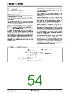
PIC12CE67X
Other peripherals can not generate interrupts since
during SLEEP, no on-chip Q clocks are present.
9.8
Power-down Mode (SLEEP)
Power-down mode is entered by executing a SLEEP
When the SLEEPinstruction is being executed, the next
instruction (PC + 1) is pre-fetched. For the device to
wake-up through an interrupt event, the corresponding
interrupt enable bit must be set (enabled). Wake-up is
regardless of the state of the GIE bit. If the GIE bit is
clear (disabled), the device continues execution at the
instruction after the SLEEPinstruction. If the GIE bit is
set (enabled), the device executes the instruction after
the SLEEP instruction and then branches to the inter-
rupt address (0004h). In cases where the execution of
the instruction following SLEEP is not desirable, the
user should have a NOPafter the SLEEPinstruction.
instruction.
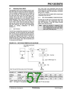
If enabled, the Watchdog Timer will be cleared but
keeps running, the PD bit (STATUS<3>) is cleared, the
TO (STATUS<4>) bit is set, and the oscillator driver is
turned off. The I/O ports maintain the status they had,
before the SLEEP instruction was executed (driving
high, low, or hi-impedance).
For lowest current consumption in this mode, place all
I/O pins at either VDD, or VSS, ensure no external cir-
cuitry is drawing current from the I/O pin, power-down
the A/D, disable external clocks. Pull all I/O pins, that
are hi-impedance inputs, high or low externally to avoid
switching currents caused by floating inputs. The
T0CKI input if enabled should also be at VDD or VSS for
lowest current consumption. The contribution from on-
chip pull-ups on GPIO should be considered.
9.8.2
WAKE-UP USING INTERRUPTS
When global interrupts are disabled (GIE cleared) and
any interrupt source has both its interrupt enable bit
and interrupt flag bit set, one of the following will occur:
The MCLR pin if enabled must be at a logic high level
(VIHMC).
• If the interrupt occurs before the the execution of
a SLEEPinstruction, the SLEEPinstruction will
complete as a NOP. Therefore, the WDT and
WDT postscaler will not be cleared, the TO bit will
not be set and PD bits will not be cleared.
9.8.1
WAKE-UP FROM SLEEP
The device can wake up from SLEEP through one of
the following events:
• If the interrupt occurs during or after the execu-
tion of a SLEEPinstruction, the device will imme-
diately wake up from sleep . The SLEEP
instruction will be completely executed before the
wake-up. Therefore, the WDT and WDT
1. External reset input on MCLR pin.
2. Watchdog Timer Wake-up (if WDT was
enabled).
3. GP2/INT interrupt, interrupt GPIO port change,
or some Peripheral Interrupts.
postscaler will be cleared, the TO bit will be set
and the PD bit will be cleared.
External MCLR Reset will cause a device reset. All
other events are considered a continuation of program
execution and cause a "wake-up". The TO and PD bits
in the STATUS register can be used to determine the
cause of device reset. The PD bit, which is set on
power-up, is cleared when SLEEP is invoked. The TO
bit is cleared if a WDT time-out occurred (and caused
wake-up).
Even if the flag bits were checked before executing a
SLEEP instruction, it may be possible for flag bits to
become set before the SLEEPinstruction completes.To
determine whether a SLEEPinstruction executed, test
the PD bit. If the PD bit is set, the SLEEP instruction
was executed as a NOP.
To ensure that the WDT is cleared, a CLRWDTinstruc-
tion should be executed before a SLEEPinstruction.
The following peripheral interrupt can wake the device
from SLEEP:
1. A/D conversion (when A/D clock source is RC).
DS40181B-page 58
Preliminary
1998 Microchip Technology Inc.

 MICROCHIP [ MICROCHIP ]