KSZ8795CLX
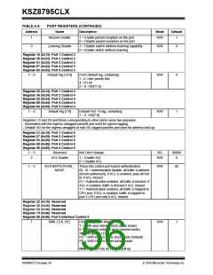
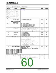
TABLE 4-4:
Address
1
PORT REGISTERS (CONTINUED)
Name
Description
Mode
Default
Receive Enable
1 = Enable packet reception on the port.
0 = Disable packet reception on the port.
R/W
1
0
Learning Disable
1 = Disable switch address learning capability.
0 = Enable switch address learning.
R/W
0
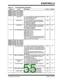
Register 19 (0x13): Port 1 Control 3
Register 35 (0x23): Port 2 Control 3
Register 51 (0x33): Port 3 Control 3
Register 67 (0x43): Port 4 Control 3
Register 83 (0x53): Port 5 Control 3
7 0
Default Tag [15:8]
Port’s default tag, containing:
7 5: User priority bits
4: CFI bit
R/W
0
3 0: VID[11:8]
Register 20 (0x14): Port 1 Control 4
Register 36 (0x24): Port 2 Control 4
Register 52 (0x34): Port 3 Control 4
Register 68 (0x44): Port 4 Control 4
Register 84 (0x54): Port 5 Control 4
7 0
Default Tag [7:0]
Default Port 1’s tag, containing:
7 0: VID[7:0]
R/W
1
Registers 19 and 20 (and those corresponding to other ports) serve two purposes:
- Associated with the ingress untagged packets and used for egress tagging.
- Default VID for the ingress untagged or null-VID-tagged packets and used for address look-up.
Register 21 (0x15): Port 1 Control 5
Register 37 (0x25): Port 2 Control 5
Register 53 (0x35): Port 3 Control 5
Register 69 (0x45): Port 4 Control 5
Register 85 (0x55): Port 5 Control 5
7 3
Reserved
N/A Don’t change.
RO
00000
0
2
ACL Enable
1 = Enable ACL
0 = Disable ACL
R/W
1 0
AUTHENTICATION_- These bits control port-based authentication:
R/W
00
MODE
00, 10 = Authentication disable, all traffic is allowed
(forced-authorized), if ACL is enabled, pass all traf-
fic if ACL missed
01 = Authentication enabled, all traffic is blocked, if
ACL is enabled, traffic is blocked if ACL missed
11 = Authentication enabled, all traffic is trapped to
CPU port, if ACL is enabled, traffic is trapped to
port 5 CPU port only if ACL missed.
Register 22 (0x16): Reserved
Register 38 (0x26): Reserved
Register 54 (0x36): Reserved
Register 70 (0x46): Reserved
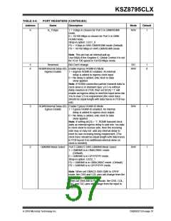
Register 86 (0x56): Port 5 Interface Control 6
7
RMII_CLK_SEL
Port 5 SW5-RMII Mode Select
R/W
1
1 = RMII uses internal clock (clock mode)
0 = RMII uses external clock (normal mode)
Strap-in option: LED2_1
PU = SW5-RMII is in the clock mode (Default)
PD = SW5-RMII is in the normal mode.
Note: This pin has an internal pull-up
DS00002112A-page 56
2016 Microchip Technology Inc.

 MICREL [ MICREL SEMICONDUCTOR ]