KSZ8795CLX
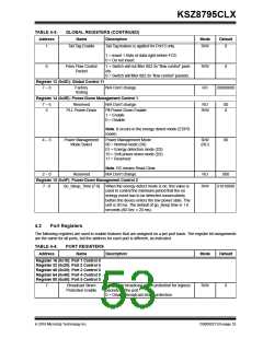
TABLE 4-3:
Address
1
GLOBAL REGISTERS (CONTINUED)
Name
Description
Mode
Default
Tail Tag Enable
Tail Tag feature is applied for Port 5 only.
R/W
0
1 = Insert 1 Byte of data right before FCS.
0 = Do not insert.
0
Pass Flow Control
Packet
1 = Switch will not filter 802.3x “flow control” pack-
ets.
0 = Switch will filter 802.3x “flow control” packets.
R/W
RO
0
Register 13 (0x0D): Global Control 11
7 – 0
Factory
Testing
N/A Don’t change.
00000000
Register 14 (0x0E): Power-Down Management Control 1
7 6
Reserved
N/A Don’t change.
RO
00
0
5
PLL Power-Down
Pll Power-Down Enable:
1 = Enable
R/W
0 = Disable
Note: It occurs in the energy detect mode (EDPD
mode)
4 – 3
Power Management
Mode Select
Power Management Mode :
00 = Normal mode (D0)
R/W
(RC)
00
01 = Energy detection mode (D2)
10 = Soft power-down mode (D3)
11 = Reserved
Note: RC means Read Clear.
2 0
Reserved
N/A Don’t change.
RO
000
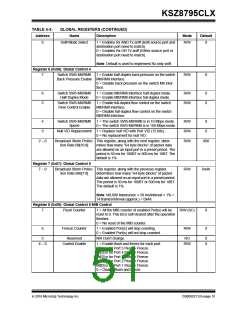
Register 15 (0x0F): Power-Down Management Control 2
7 - 0
Go_Sleep_Time [7:0]
When the energy-detect mode is on, this value is
used to control the minimum period that the no
energy event has to be detected consecutively
before the device enters the low power state. The
unit is 20 ms. The default of go_sleep time is 1.6
seconds (80 Dec × 20 ms).
R/W
01010000
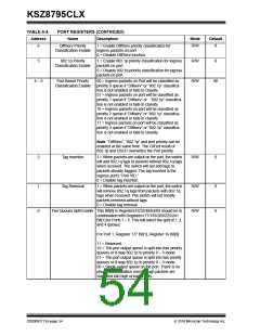
4.2
Port Registers
The following registers are used to enable features that are assigned on a per port basis. The register bit assignments
are the same for all ports, but the address for each port is different, as indicated.
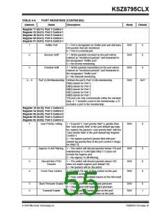
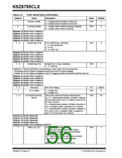
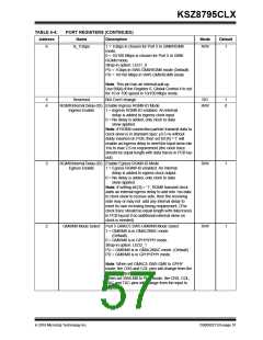
TABLE 4-4:
Address
PORT REGISTERS
Name
Description
Mode
Default
Register 16 (0x10): Port 1 Control 0
Register 32 (0x20): Port 2 Control 0
Register 48 (0x30): Port 3 Control 0
Register 64 (0x40): Port 4 Control 0
Register 80 (0x50): Port 5 Control 0
7
Broadcast Storm
Protection Enable
1 = Enable broadcast storm protection for ingress
packets on the port.
R/W
0
0 = Disable broadcast storm protection.
2016 Microchip Technology Inc.
DS00002112A-page 53

 MICREL [ MICREL SEMICONDUCTOR ]