KSZ8795CLX
TABLE 4-3:
Address
0
GLOBAL REGISTERS (CONTINUED)
Name
Description
Mode
Default
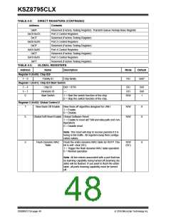
Sniff Mode Select
1 = Enables Rx AND Tx sniff (both source port and
destination port need to match).
R/W
0
0 = Enables Rx OR Tx sniff (Either source port or
destination port need to match).
Note: Default is used to implement Rx only sniff.
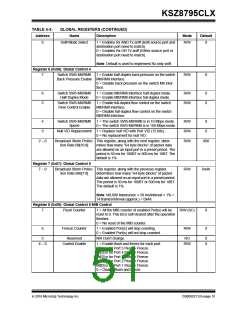
Register 6 (0x06): Global Control 4
7
Switch SW5-MII/RMII
1 = Enable half-duplex back pressure on the switch
R/W
0
Back Pressure Enable MII/RMII interface.
0 = Disable back pressure on the switch MII inter-
face.
6
5
Switch SW5-MII/RMII
Half-Duplex Mode
1 = Enable MII/RMII interface half-duplex mode.
0 = Enable MII/RMII interface full-duplex mode.
R/W
R/W
0
0
Switch SW5-MII/RMII
Flow Control Enable
1 = Enable full-duplex flow control on the switch
MII/RMII interface.
0 = Disable full-duplex flow control on the switch
MII/RMII interface.
4
3
Switch SW5-MII/RMII
Speed
1 = The switch SW5-MII/RMII is in 10 Mbps mode.
0 = The switch SW5-MII/RMII is in 100 Mbps mode.
R/W
R/W
R/W
0
0
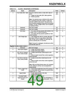
Null VID Replacement 1 = Replace null VID with Port VID (12 bits).
0 = No replacement for null VID.
2 0
Broadcast Storm Protec- This register, along with the next register, deter-
000
tion Rate Bit[10:8]
mines how many “64 byte blocks” of packet data
are allowed on an input port in a preset period. The
period is 50 ms for 100BT or 500 ms for 10BT. The
default is 1%.
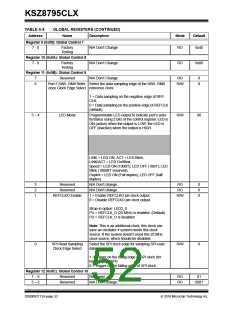
Register 7 (0x07): Global Control 5
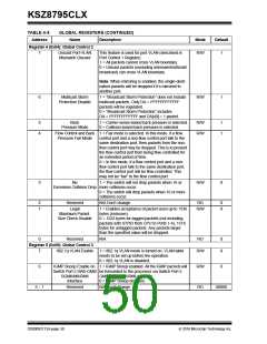
7 0 Broadcast Storm Protec- This register, along with the previous register,
R/W
0x4A
tion Rate Bits[7:0]
determines how many “64-byte blocks” of packet
data are allowed on an input port in a preset period.
The period is 50 ms for 100BT or 500 ms for 10BT.
The default is 1%.
Note:148,800 frames/sec × 50 ms/interval × 1% =
74 frames/interval (approx.) = 0x4A.
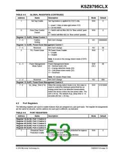
Register 8 (0x08): Global Control 6 MIB Control
7
Flush Counter
1 = All the MIB counter of enabled Port(s) will be
reset to 0. This bit is self-cleared after the operation
finishes.
R/W (SC)
R/W
0
0
0 = No reset of the MIB counter.
6
Freeze Counter
1 = Enabled Port(s) will stop counting.
0 = Enabled Port(s) will not stop counted.
5
Reserved
N/A Don’t change.
RO
0
0
4 0
Control Enable
1 = Enable flush and freeze for each port.
Bit[4] is for Port 5 Flush + Freeze.
Bit[3] is for Port 4 Flush + Freeze.
Bit[2] is for Port 3 Flush + Freeze.
Bit[1] is for Port 2 Flush + Freeze.
Bit[0] is for Port 1 Flush + Freeze.
0 = Disable flush and freeze.
R/W
2016 Microchip Technology Inc.
DS00002112A-page 51

 MICREL [ MICREL SEMICONDUCTOR ]